
Instruction manual


ECLIPSE OMEGA MATRIX INSTRUCTION MANUAL
1-5
“Configurations”—which are the operating parameters of complete system
setups, can be created from the connected computer. You can store four complete
system configurations in the computer’s memory to retrieve and activate when
needed.
The Eclipse Configuration System runs on three versions of Windows: Windows
XP, Windows Server 2003 and Windows 2000. When running ECS on the
three Windows operating systems, the client and server can run on separate
machines connected over a network.
From the Eclipse Configuration Software, you can create point-to-point and
fixed group or party-line communications among the connected audio devices,
assign a “label” to each port/panel, and inhibit or enable features at any
connected panel. You can set up the system to run on a client/server model over a
network, allowing you to control the matrix remotely.
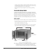
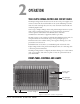
INTERCOM PANELS AND ACCESSORY PANELS
All intercom panels connect to the central matrix via shielded category-5 cable
terminated with RJ-45 connectors. The shielded category-5 cable connects to the
matrix through the MVX-A16 analog circuit card. The following Clear-Com
intercom panels are compatible with the Eclipse Omega matrix system:
• i-Station family, including expansion panels
• ICS-2003 intercom panels, including expansion panels
• ICS-52 and ICS-92 intercom panels, including expansion panels
• ICS-62 and ICS-102 intercom panels, including expansion panels
• ICS-1008 and ICS-1016 intercom panels, including expansion panels
• 4215E, 4224E, 4226E, 4294E, 4212E, 4222E, 4203E, 4206E, 4230E and
4230VE 4000 Series II panels
• V12LD, V24LD, V12PD, V24PD, V12LDD, V12LDE and V12PDE
V-Series panels
Each of these panels is described in its own manual. For a full description of the
operation, installation, and maintenance of a panel, refer to the appropriate panel
instruction manual.
INTERFACES
Interface modules convert the 4-wire signals of a central matrix port to other
types of signals that communicate with devices such as telephones, camera
intercoms, two-way radios, and so on. In this way non-4-wire devices can
communicate with the central matrix.
Each interface module has hardware connectors to connect to both the central
matrix and to the external device that communicates with the central matrix.
Most interface modules connect to the central matrix via shielded category-5
cable terminated with RJ-45 connectors. The DIG-2 digital interface module,
however, connects to the central matrix via double-shielded 24 AWG conductor
category-6 enhanced (CAT-6E) STP cable.