
Instruction manual


Clear-Com Communication Systems
Eclipse Matrix Installation Instruction Manual
4-7
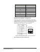
Table 4-2: Pin Connection for PC DB-25F to Eclipse PiCo Cable
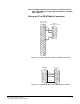
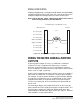
WIRING FOR ETHERNET CONNECTION
To connect the matrix to a local-area network (LAN), use the RJ-45
sockets labeled “LAN 1” and “LAN 2” on the rear of the Eclipse Omega
and Median matrices, or the RJ-45 socket labeled “LAN” on the rear of
the Eclipse Pico and Eclipse-32 matrices. The connectors have
standard Ethernet pin assignments, shown in Figure 4-3.
Figure 4-3: Pin Assignments for LAN 1 and LAN 2 Connectors
Note: Shielded CAT-5 cable should be used.
17 N/C
18 N/C
19 N/C
20 N/C
21 N/C
22 N/C
23 N/C
24 N/C
25 N/C
PC Connection (DB-25F) Eclipse PiCo (3.5 mm jack)
8
7
6
5
4
3
2
1
LAN1 and LAN2
Ethernet RJ-45 Connectors
PIN
FUNCTION
1
2
3
4
5
6
7
8
Transmit data +
Transmit data
Receive data +
Unused
Unused
Receive data
Unused
Unused