
Instruction manual


Clear-Com Communication Systems
Eclipse Matrix Installation Instruction Manual
4-6
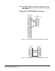
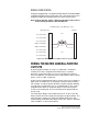
Wiring for PC to 3.5mm Jack Matrix Connector
On the PC end, a DB-9F or DB-25F connector is used. Make sure that
the data connections of pin 2 to jack plug tip and pin 3 to jack plug ring
are followed, and that pin 5 (DB-9F) or pin 7 (DB-25F) goes through to
the jack plug screen. The cable will now be ready to use. Table 4-1
gives the connection information for the DB-9F and Table 4-2 gives the
connections for the DB-25F.
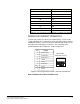
Table 4-1: Pin Connection for PC DB-9F to Eclipse PiCo Cable
PC Connection (DB-9F) Eclipse PiCo (3.5 mm jack)
1N/C
2Tip
3Ring
4N/C
5Screen
6N/C
7N/C
8N/C
9N/C
PC Connection (DB-25F) Eclipse PiCo (3.5 mm jack)
1N/C
2Tip
3Ring
4N/C
5N/C
6N/C
7Screen
8N/C
9N/C
10 N/C
11 N/C
12 N/C
13 N/C
14 N/C
15 N/C
16 N/C