
Instruction manual


Clear-Com Communication Systems
Eclipse Matrix Installation Instruction Manual
3-6
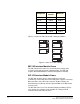
Table 3-1: Interface Current Consumption
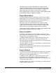
Figure 3-1 shows the PSU-101 to IMF-3 wiring possibilities.
Figure 3-1: PSU-101 to IMF-3 Wiring
IMF-102 Interface Module Frame
The IMF-102 interface frame has an internal power supply and a
rear-panel connector to provide redundant power. The IMF-102
requires 90 to 250 VAC with a maximum dissipation of 20 watts.
DIF-102 Interface Module Frame
The DIF-102 interface frame is powered by one or two (for
redundancy) external AC mains to 24 VDC power supplies via locking
DIN connectors on the DIF-102 rear panel. All other voltages are
derived directly or indirectly from the input 24 VDC on the DIG-2 front
and rear cards.
The DIF-102 frame has a PSU fail-alarm output provided by Form C
relay change-over contacts made available on a 9-way make D
connector on the DIF-102 rear panel.
Component
Average
Current
Maximum
IMF-3 Frame 0.20 A 0.20 A
CCI-22 0.00 A 0.00 A
FOR-22 0.07 A 0.15 A
TEL-14 0.28 A 0.37 A
RLY-6 0.10 A 0.15 A
GPI-6 0.02 A 0.02 A
PSU-101
IMF-3
IMF-3
IMF-3
IMF-3
IMF-3
PSU-101
PSU-101