ECLIPSE MATRIX INSTALLATION Instruction Manual
Eclipse Matrix Installation Instruction Manual © 2007, 2009 Vitec Group Communications. All rights reserved. Part Number 810298Z Rev. 7 Vitec Group Communications LLC 850 Marina Village Parkway Alameda, CA 94501 U.S.A. Vitec Group Communications Ltd 7400 Beach Drive IQ Cambridge Cambrideshire United Kingdom CB25 9TP The Vitec Group plc Beijing Representative Office Room 706, Tower B Derun Building, YongAn Dongli A No.3 Jianwai Ave., Chaoyang District Beijing, P.R.
CONTENTS INSTALLATION OVERVIEW . . . . . . . . . . . . . . . . . . 1-1 Introduction . . . . . . . . . . . . . . . . . . . . . . . . . . . . . . . . . . . . . . . 1-1 Step-by-Step Installation . . . . . . . . . . . . . . . . . . . . . . . . . . . . . 1-3 Verify the Shipment. . . . . . . . . . . . . . . . . . . . . . . . . . . . . . . . . . . 1-3 Select Locations for the Components . . . . . . . . . . . . . . . . . . . . . 1-3 Determine the Wiring Requirements . . . . . . . . . . . . . . . . . . . . . .
Eclipse Omega Matrix . . . . . . . . . . . . . . . . . . . . . . . . . . . . . . . . 3-1 Eclipse Median Matrix . . . . . . . . . . . . . . . . . . . . . . . . . . . . . . . . 3-2 Eclipse Pico Matrix . . . . . . . . . . . . . . . . . . . . . . . . . . . . . . . . . . 3-2 Eclipse-32 Matrix . . . . . . . . . . . . . . . . . . . . . . . . . . . . . . . . . . . . 3-2 Intercom Panels . . . . . . . . . . . . . . . . . . . . . . . . . . . . . . . . . . . . . . 3-3 V-Series Panels and Expansion Panels . . . . . . .
FOR-22 4-Wire/Radio Interface Wiring . . . . . . . . . . . . . . . . . . . . 4-20 External Audio Devices . . . . . . . . . . . . . . . . . . . . . . . . . . . . . . 4-20 Call Signal Input. . . . . . . . . . . . . . . . . . . . . . . . . . . . . . . . . . . . 4-21 Relay Contacts . . . . . . . . . . . . . . . . . . . . . . . . . . . . . . . . . . . . 4-21 CCI-22 Party-Line Interface Wiring . . . . . . . . . . . . . . . . . . . . . . . 4-21 Clear-Com Party Lines General Discussion . . . . . . . . . . . . . .
Tie-Line (Audio Only) Linking . . . . . . . . . . . . . . . . . . . . . . . . . 5-5 GLOSSARY . . . . . . . . . . . . . . . . . . . . . . . . . . . . . . . 6-1 Eclipse Manuals . . . . . . . . . . . . . . . . . . . . . . . . . . . . . . . . . . . 6-5 Software Manuals . . . . . . . . . . . . . . . . . . . . . . . . . . . . . . . . . . . . . 6-5 Hardware Manuals . . . . . . . . . . . . . . . . . . . . . . . . . . . . . . . . . . . . 6-5 LIMITED WARRANTY . . . . . . . . . . . . . . . . . . . . . . .
FIGURES Figure 2-1 IMF-3 Interface Frame Rear Panel................................. 2-4 Figure 2-2 IMF-102 Interface Frame Rear Panel............................. 2-4 Figure 3-1 PSU-101 to IMF-3 Wiring ............................................... 3-6 Figure 4-1 Computer DB-25F to Matrix DB-9M RS-232 Cable........ 4-5 Figure 4-2 Computer DB-9F to Matrix DB-9M RS-232 Cable.......... 4-5 Figure 4-3 Pin Assignments for LAN 1 and LAN 2 Connectors .......
ii Clear-Com Communication Systems Eclipse Matrix Installation Instruction Manual
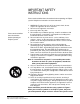
IMPORTANT SAFETY INSTRUCTIONS Please read and follow these instructions before operating an Eclipse system. Keep these instructions for future reference. Please read and follow these instructions before operating an Eclipse system. 1. WARNING: To reduce the risk of fire or electric shock, do not expose this apparatus to rain or moisture. 2. Do not use the apparatus near water. 3. Clean only with a dry cloth. 4. Do not block any ventilation openings.
improperly. They also refer you to important operating and maintenance instructions in the manual. CAUTION RISK OF ELECTRIC SHOCK DO NOT OPEN This symbol alerts you to the presence of uninsulated dangerous voltage within the product’s enclosure that might be of sufficient magnitude to constitute a risk of electric shock. Do not open the product’s case. This symbol informs you that important operating and maintenance instructions are included in the literature accompanying this product.
1 INSTALLATION OVERVIEW INTRODUCTION The Eclipse Matrix Installation Instruction Manual describes the steps required to install an Eclipse matrix system and customize it. The manual provides information about placing, powering, and wiring components of the Eclipse system. This manual describes how to install an Eclipse matrix system. It is highly recommended that the instruction manual for the matrix to be installed is read before attempting an installation.
Chapter 5. Connecting Matrices The fifth chapter provides information on linking matrices.
STEP-BY-STEP INSTALLATION To install an Eclipse matrix system: 1. Verify the shipment. 2. Select locations for the components. 3. Determine the wiring requirements. 4. Install components in rack. 5. Install cables. 6. Connect cable and auxiliary wiring. 7. Connect to mains AC Power. 8. Configure the system with the Eclipse Configuration System (ECS) software. 9. Verify the operation of the system. 1. Verify the Shipment When the equipment is received inspect the boxes for shipping damage.
4. Install Components in Rack Install the matrix in a standard Electronics Industry Association 19-inch wide (48.26 cm) equipment rack. The matrix requires adequate ventilation. Leave at least 2 inches (50.8 mm) of clearance on all sides of the matrix to ensure proper airflow. Do not block ventilation vents. Check the position of circuit cards, power supplies, and rear-connector panels.
connectors on the rear of the associated IMF-3 frame per the actual application. Special interfaces such as the RLY-6 and GPI-6 are connected directly via an RJ-45 connector on the rear of the matrix to the appropriate interface input connector on an IMF-3 frame. External Computer - To connect the computer to the Eclipse matrix, use the supplied DB-9 cable or a commercially available shielded RS-232 cable.
Panels V-Series Panels Each V-Series panel (V12LD, V12PD, V24LD, V24PD, V12LDD, V12PDD, V12LDE, V12PDE) has an external power supply. AC voltage for these panels can be 100 to 240 VAC without any switching or fuse changes. 4000 Series II Panels Each 4000 Series II panel (4212, 4215, 4222, 4224, 4226, 4294, 4203, 4206, 4230, 4230V) has an external power supply. AC voltage for these panels can be 100 to 240 VAC without any switching or fuse changes.
Matrix Indicators to Verify Eclipse Omega There are many lights on the front of the matrix that indicate its operational status. Proper operation of the matrix is indicated by the following: 1. The two power supply lights, labeled “+5V” and “+3.3V” illuminate green steadily to indicate that the power supplies are present. 2. The dot-matrix array of lights displays a number to indicate which of the four stored configurations in the CPU card’s memory is currently operating.
Eclipse-32 The following front-panel indicators indicate a properly operating Eclipse-32 matrix: 1. The two PSU alarm lights, labeled “1” and “2” do not illuminate under normal operating conditions. 2. One of the four green configuration lights illuminates steadily to identify the currently active configuration. 3. The “OK” light flashes to indicate that the Eclipse-32 is running successfully. 4. If the matrix is connected to a local area network, the green LAN UP light illuminates steadily.
2 PLACING SYSTEM COMPONENTS COMPONENT LOCATION REQUIREMENTS This chapter provides guidelines for placing and arranging the main components of an Eclipse system, including: • Eclipse matrices • Interface frame(s) and power supplies • Intercom panels and accessory panels • External computer ECLIPSE MATRICES The Eclipse matrix is the central connecting point of the system. All panels, interfaces, and external devices must be connected directly to the Eclipse matrix, so it should be centrally located.
lights allow the system operator to identify and correct the alarm conditions. See the Eclipse Omega Matrix Instruction Manual (part 810290Z) for more details. Caution: It is mandatory that the air flow through an Eclipse Omega matrix from the bottom to the top is unimpeded.
Caution: It is mandatory that the air flow across an Eclipse Pico matrix is unimpeded. The air flow in a standard 19-inch (48.26 cm) rack should be sufficient. If the matrix is mounted in a portable case, be sure the air flow is not impeded. Eclipse-32 Matrix The Eclipse-32 matrix requires one vertical rack unit (1.75 in. or 44.45 mm) in a standard Electronics Industry Association 19-inch (48.26 cm) rack. A temperature-controlled fan cools the Eclipse-32 and forces air through the unit horizontally.
POWER SUPPLY #1 CH. A Matrix CH. A Matrix CH. A Matrix CH. A Matrix CH. A Matrix CH. A Matrix CH. A Matrix CH. A Matrix CH. A Matrix CH. A Matrix CH. A Matrix CH. A I/O PHONE LINE A CH. A I/O PHONE LINE A CH. A I/O PHONE LINE A CH. A I/O PHONE LINE A CH. A I/O PHONE LINE A CH. A I/O PHONE LINE A CH. A I/O PHONE LINE A CH. A I/O PHONE LINE A CH. A I/O PHONE LINE A CH. A I/O PHONE LINE A CH. A I/O PHONE LINE A CH. B Matrix CH. B Matrix CH. B Matrix CH. B Matrix CH. B Matrix CH.
DIF-102 Interface Module Frame The DIF-102 interface frame has slots for two digital DIG-2 interface modules in one rack unit (1 RU) of a standard Electronics Industry Association 19-inch (48.26 cm) rack. DIG-2 interface modules allow the matrix to connect to digital versions of Clear-Com intercom panels. The DIF-102 frame is powered by one or two (for redundancy) external AC mains to 24 VDC power supplies via locking DIN connectors on the DIF-102 rear panel.
2-6 Clear-Com Communication Systems Eclipse Matrix Installation Instruction Manual
3 POWERING SYSTEM COMPONENTS POWER REQUIREMENTS Each matrix is equipped with two power supplies that can be connected to separate branches of AC mains, providing redundancy for the power supplies and the power sources. Power requirements differ for each component of an Eclipse system.
Clear-Com ships each matrix with two power supplies already installed. When the matrix is received, connect each of the power supplies to a dedicated branch of AC mains power using the IEC power connectors on the Eclipse Omega frame’s rear panel. A fully equipped Eclipse Omega frame requires 100 to 240 VAC at 50 to 60 Hz with a maximum dissipation of 300 W. Eclipse Median Matrix The Eclipse Median matrix has two internal, Euro Cassette, plug-in power supplies.
An Eclipse-32 matrix requires 100 to 240 VAC at 50 to 60 Hz with a maximum dissipation of 40W. INTERCOM PANELS V-Series Panels and Expansion Panels Each V-Series panel or expansion panel has a separate external DC power supply. The power supply is “universal”, operating over a voltage range of 100 to 240 VAC at 50 to 60 Hz. The maximum dissipation is 50W. 4000 Series II Panels and Expansion Panels Each 4000 Series II panel or expansion panel has a separate external DC power supply.
XPL-12/22 Display Expansion Panels and AP-22 Assignment Panels XPL-12/22 display expansion panels and AP-type assignment panels require an external transformer identical to those used with the 1 RU panels (90 to 125 or 210 to 250 VAC at 45 to 65 Hz with a maximum dissipation of 40W).
INTERFACE MODULE FRAME POWER SUPPLY REQUIREMENTS IMF-3 Interface Module Frame As a rule-of-thumb, one PSU-101 power supply unit is required for every two IMF-3 frames. There are two exceptions to this rule. The first exception occurs when the frames have a large number of CCI-22 party-line interfaces which require no DC power from the IMF-3 frame.
Component Average Current Maximum IMF-3 Frame 0.20 A 0.20 A CCI-22 0.00 A 0.00 A FOR-22 0.07 A 0.15 A TEL-14 0.28 A 0.37 A RLY-6 0.10 A 0.15 A GPI-6 0.02 A 0.02 A Table 3-1: Interface Current Consumption Figure 3-1 shows the PSU-101 to IMF-3 wiring possibilities.
4 WIRING SYSTEM COMPONENTS SUMMARY OF WIRING SYSTEMS This chapter describes how to connect an Eclipse matrix to its remote panels and interfaces and to other Eclipse matrices using fiber-optic cable. Most panels and interfaces connect to a matrix via single 4-pair shielded RJ-45 terminated cables. For more detail about component placement, specifications of individual products, and internal adjustments, refer to the individual manual for each product.
RJ-45 CABLES The following section discusses the use of RJ-45 connectors for connecting an Eclipse frame to panels and interfaces. It includes the following topics: • General discussion about RJ-45 connector cables • Clear-Com kits and recommendation • Installing RJ-45 connectors.
not being removed from a pre-made cable this will not be a problem. Be aware that if the ends are removed from a pre-made cable to shorten or to punch onto blocks, pair 2 and 3 colors may be different. Caution: Make sure the type of RJ-45 connector matches the wire type. Connectors are available for both stranded and solid wire. Clear-Com intercom panels do not require keyed connectors. Please refer to the following list for connector vendor and port numbers.
your thumb and forefinger. Keep the jacket clamped in this retracted position until the fourth step. 2. Pull the twisted pairs to the one side and untwist them back to the edge of the vinyl jacket. Smooth the kinks out slightly by pulling the conductors through your fingers. 3. In the correct color sequence, pull one wire at a time, straight out, clamping it in place between your thumb and forefinger. If a wire must cross the others, make sure it does it inside the jacket.
Note: If the ECS computer does not have a serial port, and only offers USB, adaptors are generally available from computer parts suppliers.
Wiring for PC to 3.5mm Jack Matrix Connector On the PC end, a DB-9F or DB-25F connector is used. Make sure that the data connections of pin 2 to jack plug tip and pin 3 to jack plug ring are followed, and that pin 5 (DB-9F) or pin 7 (DB-25F) goes through to the jack plug screen. The cable will now be ready to use. Table 4-1 gives the connection information for the DB-9F and Table 4-2 gives the connections for the DB-25F. PC Connection (DB-9F) Eclipse PiCo (3.
PC Connection (DB-25F) Eclipse PiCo (3.5 mm jack) 17 N/C 18 N/C 19 N/C 20 N/C 21 N/C 22 N/C 23 N/C 24 N/C 25 N/C Table 4-2: Pin Connection for PC DB-25F to Eclipse PiCo Cable WIRING FOR ETHERNET CONNECTION To connect the matrix to a local-area network (LAN), use the RJ-45 sockets labeled “LAN 1” and “LAN 2” on the rear of the Eclipse Omega and Median matrices, or the RJ-45 socket labeled “LAN” on the rear of the Eclipse Pico and Eclipse-32 matrices.
CONNECTING MATRICES WITH FIBER-OPTIC CABLE Each fiber card link consists of a front card with various status indicators and a rear card with two Duplex LC Terminated fiber optic connectors (TXVRA and TXVRB). The fiber cards use 9/125µ Single Mode fiber optic cables. On the rear card the TX1/RX1 connector is used for the main ring and the TX2/RX2 connector is used for the secondary ring.
RJ-45 CONNECTOR AT MATRIX PORT RJ-45 CONNECTOR ON PANEL OR INTERFACE 8 765 4 321 Views from front of connectors 8 765 4 321 Shielded category-5 cables wired pin-to-pin Matrix Frame RJ-45 Pin Numbers RS-422 Input + (into Matrix) 1 RS-422 Input – (into Matrix) 2 Audio Input + (into Matrix) 3 Audio Output + (from Matrix) 4 Audio Output – (from Matrix) 5 Audio Input – (into Matrix) 6 RS-422 Output + (from Matrix) 7 RS-422 Output – (from Matrix) 8 Panel RJ-45 Pin Numbers Pair 2 Pair 1 Pair
SINGLE-PAIR DIGITAL Single-pair digital wiring is accomplished with double-shielded 24 AWG conductor CAT-6E enhanced STP cable. Pair 1 transmits and receives multiplexed digital and analog between the matrix and the panel. Note: Ensure that the “select” switch on the panel’s rear cover is in the correct position for the intended use.
Note: If the GP-OUT port is used the following filter must be fitted between the PROC-RCC socket and the cable: CINCH FA-25PS/1 25W D-type in-line 1000pF filter (UK supplier: Farnell 111-4108). Each general-purpose output has a relay inside the Eclipse Omega/Median frame. When a general-purpose output is inactive, the associated “common” pin on the GP OUT connector will be shorted to the relevant “normally closed” pin.
WIRING THE MATRIX TO GENERAL PURPOSE INPUTS It is possible to connect an external logic device such as an external foot switch, a panel-mounted switch, or the logic output of some other device to the connector labeled “GP IN” on the rear of the Eclipse matrix.
general-purpose input. A voltage output on the GP IN connector supplies the current. To select a mode, move the J1 jumper on the CPU rear card to one of two positions. (The J1 jumper is located on the inner-frame side of the DB-25 connector.) • For opto-isolated mode, fit the J1 jumper across pins 1 and 2. • For non-isolated mode, fit the J1 jumper across pins 2 and 3. Note: It is recommended that the connector is set to the fully opto-isolated mode.
NON-ISOLATED MODE Figure 4-9 shows the non-isolated connection. +3V3 +3V3 +3V3 R 33K2 R 33K2 U R29 1.5K EXTERNAL INPUT 1 R30 EXTERNAL INPUT 2 1 8 2 7 3 6 4 5 INPUT 1 INPUT 2 1.5K MOCD207-M Figure 4-9: Non-Isolated Connection to Eclipse GPI Connector To cause an input to detect an active signal, current must flow from the relevant input pin. The external device should draw no current to cause an inactive input and at least 5 mA to cause an active input.
WIRING THE MATRIX TO AN EXTERNAL ALARM With the Alarm I/O DB-9F connector, an external alarm device can be connected to monitor failures in the matrix. Pins are also available for connecting an external alarm source to the matrix’s Alarm System. For details on the functions that are monitored by the Alarm System refer to the Eclipse Omega or Eclipse Median Manuals. A failure will activate the relay contacts connected to pins 4, 5, and 9 of the connector.
WIRING THE MATRIX DIRECTLY TO A 4-WIRE AUDIO DEVICE An external 4-wire audio device can be directly connected to a port connector through the four audio pins, as shown in Figure 4-11. If there is excessive noise on the lines between this device and the matrix, the device may be electronically unbalanced with the rest of the system. The device will need to be isolated with external isolation transformers.
WIRING THE MATRIX TO INTERFACE MODULES Interface modules convert the 4-wire signals of a central matrix port to some other form of communication, such as telephones, camera intercoms, two-way radios, and so on. In this way, non-4-wire devices can communicate with the central matrix. Each interface module has hardware connectors to connect to both the central matrix and to the external device that communicates with the central matrix.
DIG-2—The DIG-2 digital interface rear cards provide RJ-45 connections to ICS digital panels and Eclipse matrices. For wiring details refer to the DIG-2/DIF-102 manual (part. no. 810311Z). TEL-14—The TEL-14 interface is a two-channel device and uses each of the RJ-45 connectors on its rear panel for connection to the matrix port. The top RJ-45 is for Line A of the interface and the lower RJ-45 is for Line B of the interface.
Ports Rear View of IMF-3 Frame GPI/RLY Interface Connector RJ-45 RJ-45 RJ-45 RJ-45 RJ-45 DB-9 DB-9 DB-9 DB-9 DB-9 RJ-45 RJ-45 RJ-45 RJ-45 RJ-45 DB-9 DB-9 DB-9 DB-9 DB-9 Other Interfaces RLY-6 #2 RLY-6 #1 GPI-6 #2 GPI-6 #1 Figure 4-12: RLY-6/GPI-6 Daisy Chain Connection Figure 4-13 shows the pin assignments of RJ-45 connectors when used to connect to interfaces (IMF-3 frames).
FOR-22 4-WIRE/RADIO INTERFACE WIRING The FOR-22 4-wire/radio interface connects two external 4-wire circuits to the matrix. Camera intercoms, two-way radios, microwave and satellite links, IFBs, and program audio in and out are candidates for use with the FOR-22. A FOR-22 interface connects to an Eclipse matrix through the two RJ-45 connectors on the IMF-3 or IMF-102 rear panel assembly to which the FOR-22 is connected. One RJ-45 connector is for the first channel of the interface.
various level ranges available on the input and output refer to the FOR-22 manual (part 810306Z). Call Signal Input The Call Signal input is used to receive a call/logic input signal from an external device and send it to the matrix. The voltage across the pins required to receive a call signal ranges from 4 to 50V; it can be either positive or negative polarity or AC. The input will draw between 4 and 8 mA.
Channel 1 Channel 2 CC/RTS 6 Ground 7 +30 VDC Power 8 Audio 9 1 CC/RTS 2 Ground 3 +30 VDC Power 4 Audio 5 Figure 4-15: Pinout of the DB-9M Interface I/O Connectors for CCI-22 Clear-Com Party Lines General Discussion Stations on Clear-Com party lines connect to each other with two-conductor shielded microphone cable.
calls directly to or from any intercom panel in an Eclipse or other system. The TEL-14 interface has its own manual in the Eclipse manual set. This following discussion gives an overview of the wiring of this interface. The TEL-14 uses each of the RJ-45 connectors on its rear panel for connection to a matrix port. One RJ-45 is for Line A of the interface and the other RJ-45 is for Line B of the interface. The DB-9M connectors are the Line A and Line B connections to the telephone line.
The leftmost DB-9M connector is used to connect to the first telephone line, A. The leftmost RJ-45 connector is used to connect telephone line A to the matrix frame. The rightmost DB-9M connector is used to connect to the second telephone line, B. The rightmost RJ-45 connector is used to connect the telephone line B to the matrix. Figure 4-17 illustrates the wiring of one IMF-102 rear-panel assembly to a TEL-14 interface. Connects to the first telephone line, A. Connects telephone line A to the matrix. CH.
DB-9 to TEL-14 Line 1 6 Phone Line 2 7 Relay 3 8 Relay RJ-11 to Telephone Line RJ-11 to DB-9F Adapter Clear-Com Part Number 770025 1 Phone (Blue 2 Relay (Yellow) 3 Line (Gray) 4 Line (Red) 5 Relay (Black) 6 Phone (Gray) 4 9 Phone 5 Figure 4-18: RJ-11 to DB-9 Adaptor for TEL-14 Interfaces Note: The TEL-14 interface works with telephone company central office (CO) lines. Analog panel lines from some in-house PABXs are not compatible.
and GPI-6 modules can be mixed together up to the total limit of 60 items. Five RLY-6 and five GPI-6 modules would provide 30 relays and 30 inputs for a total of 60 inputs and outputs. Note: For Eclipse systems if both GPI-6 and RLY-6 interfaces are used the GPI-6 interfaces must be placed first in the daisy chain. This restriction does not apply to Matrix Plus 3 systems where interfaces can be mixed in this 'daisy-chained' scheme.
Ports Rear View of IMF-3 Frame GPI/RLY Interface Connector RJ-45 RJ-45 RJ-45 RJ-45 RJ-45 DB-9 DB-9 DB-9 DB-9 DB-9 RJ-45 RJ-45 RJ-45 RJ-45 RJ-45 DB-9 DB-9 DB-9 DB-9 DB-9 Other Interfaces RLY-6 #2 RLY-6 #1 GPI-6 #2 GPI-6 #1 Figure 4-19: Rear View of IMF-3 Frame To External Device To connect external devices to an RLY-6 interface, use the two DB-9M connectors on the rear cable assembly panel for the interface.
1 6 #1/4 Normally Closed #1/4 COM 2 #1/4 Normally Open #2/5 Normally Closed 7 3 8 #2/5 COM #2/5 Normally Open 4 9 #3/6 Normally Closed #3/6 COM 5 #3/6 Normally Open Figure 4-20: RLY-6 Interface DB-9M Connector Pinout IMF-102 Interface Module Frame Wiring The wiring of an RLY-6 interface that is placed in an IMF-102 interface frame is the same as the wiring for a RLY-6 interface placed in an IMF-3 interface frame.
GPI-6 INTERFACE WIRING The GPI-6 input interface module provides connection of six programmable inputs to the matrix so that each input can control a predefined matrix function. Multiple GPI-6 interfaces can be daisy-chained to provide connection of up to 60 inputs to the matrix. RLY-6 and GPI-6 modules can be mixed together up to the total limit of 60 items. Five RLY-6 and five GPI-6 modules would provide 30 relays and 30 inputs for a total of 60 inputs and outputs.
GPI-6 I/O DB 9M 1 #1/4 Input A 6 #1/4 Input B #2/5 Input A 2 #2/5 Input B 7 3 #3/6 Input A 8 #3/6 Input B Ground 4 9 Power Source Ground 5 Figure 4-21: GPI-6 Interface DB-9M Connector Pinout GPI-6 I/O DB-9M GPI-6 I/O DB-9M 1 1 6 6 2 2 7 7 3 3 8 8 4 9 X 4 5 X X 9 5 X Figure 4-22: GPI-6 Application Examples Figure 4-21 and Figure 4-22 show how to connect switches or contacts using the power source provided by the GPI-6 module or powering switches from external sources.
Refer to the respective manuals for these interfaces and frames in the Eclipse manual set for more information. Configuration To define an input function, use the Eclipse Configuration System program, as described in its manual.
WIRING AN ICS PANEL MISCELLANEOUS CONNECTOR Most local devices connect with a matrix panel via the “miscellaneous” connector. The following sections discuss how to wire the various functions available on the “miscellaneous” connector. • External program feed input • Binaural headset (All Panels Except ICS-2003/2110/1016) • Logic input #1 and logic input #2 • Mute relay contacts • Auxiliary relay contacts.
feed (“program audio”) can be heard on the panel’s speaker and headset; it cannot be heard by other panels in the matrix. To connect an external program feed to the panel, connect the balanced audio pair to pins 1 and 9, and connect a shield or ground connection if available to pin 2 of the connector (refer to Figure 4-23). BINAURAL HEADSET (ALL PANELS EXCEPT ICS-2003/2110/1016) The second ear output allows an external binaural headset to be connected to the panel.
details on setting this jumper. The ICS-2003 only supports an active low input on both inputs. Use normally open type switches to activate the logic inputs. Connect the switches as follows (refer to Figure 4-23): • Logic Input #1—pins 4 to 5 (pin 4 = ground) • Logic Input #2—Pins 11 to 12 (pin 11 = ground) Do not apply external voltage to the logic inputs, except in the case of Logic Input #2 being configured for an active high input as described above.
WIRING A BINAURAL HEADSET (ICS-2003) The ICS-2003 has a second earphone output, but it functions and is wired differently from all other ICS panels. This output is not available on the “miscellaneous” connector, but on the main board of the panel on a separate header connector. If a six pin headset connector were installed on the front or rear of the panel, this output would be available. The default configuration of the panel has both earphone outputs being fed with both intercom and program audio.
WIRING AN ICS PANEL OPT-100 AUXILIARY AUDIO I/O OPTION Figure 4-25 shows the pinout of the DB-15F “auxiliary audio I/O” connector on the back of the intercom panel. The sections that follow the pinout diagram describe each function and how to wire for it.
AUXILIARY AUDIO LINE LEVEL OUTPUT The auxiliary audio line level output is a balanced line-level transformer-isolated feed of the same audio signal that is sent to the panel’s internal speaker. For example, this output could be used to feed an external amplifier connected to a set of ceiling loudspeakers. Connect to pins 6 and 13 for a balanced output. Pin 14 is available as a shield or ground source. Refer to Figure 4-25.
WIRING AN ICS PANEL ACCESSORY CONNECTOR An intercom panel can be connected to an accessory key panel via the accessory panel connector. To connect an accessory panel use the DB-9 connector cable supplied with the Accessory Panel. Connect the cable between the panel and the input connector of the first accessory panel. To connect a second panel use another DB-9 cable and connect it between the output connector of the first panel to the input connector of the second panel.
5 CONNECTING MATRICES Eclipse matrices can be connected to expand the geographical range or the port density of a system. With trunk lines and an Ethernet network up to 15 Eclipse matrices can be connected. Eclipse Omega and Eclipse Median matrices can also be connected using fiber-optic cable when fitted with E-FIB fiber-optic interface cards. Base-loop linking creates non-blocking access to all audio ports of two connected Eclipse Pico/Eclipse-32 matrices.
Figure 5-2: Example of Fiber-Optic Connected Matrices The serial port to serial port wiring is not a typical RJ-45 to RJ-45 jumper cable. It is possible to construct such a cable or use a punch-down block for the crossover wiring. The Seimon cable tester will not test this wiring. Figure 5-3 illustrates dedicated trunk wiring.
RJ-45 Port Connector on First Matrix Frame RJ-45 Port Connector on Second Matrix Frame RS-422 Receive + 1 1 RS-422 Receive + RS-422 Receive - 2 2 RS-422 Receive - Audio Receive + 3 3 Audio Receive + Audio Send + 4 4 Audio Send + Audio Send - 5 5 Audio Send - Audio Receive - 6 6 Audio Receive - RS-422 Send + 7 7 RS-422 Send + RS-422 Send - 8 8 RS-422 Send - Figure 5-3: Dedicated Serial Port Audio Trunk Wiring PIN 1 2 3 4 5 6 7 8 FUNCTION Transmit data + Transmit data Recei
Eclipse Omega Eclipse Omega Eclipse Omega Audio trunk Ethernet Long-distance transmission system: public or private telephone network, satellite-linked network, microwave network, etc. Figure 5-5: Matrices Linked Across Continents This type of connection uses up available ports on the matrix and so does not provide 100% routing. This type of connection is suitable when only a restricted amount of inter-matrix communications are required, such as between studios.
BASE-LOOP LINKING (ECLIPSE PICO/ECLIPSE-32 MATRIX ONLY) By connecting a single RJ-45 “base loop” connector on one Eclipse Pico/Eclipse-32 matrix to a second RJ-45 “base loop” connector on a second Eclipse Pico/Eclipse-32 matrix, an intelligently linked non-blocking 64-port system in two rack units (2 RU) can be created. This type of connection gives each connected matrix access to all of the audio ports of both matrices, without using up ports for trunk lines.
5-6 Clear-Com Communication Systems Eclipse Matrix Installation Instruction Manual
6 GLOSSARY Analog Port Any of the Eclipse matrix’s analog input/output RJ-45 connectors that are used to connect cable from the matrix to panels and interfaces. Each “port” connects to a separate audio channel in the matrix intercom system. Bus A bus is the channel or path between the components in the matrix along which electrical signals flow to carry information from one component to the next. In the Eclipse matrix the bus is located in the etched surface of the midplane.
Fiber-optic Cable A fiber-optic cable consists of a glass core covered with a reflective material called “cladding” and several layers of buffer coating to protect the cable from the environment. A laser sends light pulses through the glass core to the other end of the cable. FreeSpeak Digital wireless communications product. Sold under the FreeSpeak name in Europe and Asia and CellCom in USA. Full Duplex Refers to transmission of signals in two directions simultaneously. IFB “Interruptible Foldback”.
by manufacturers. Single-mode fiber evolved as production methods improved. Multiplexing The process by which two or more signals are transmitted over a single communications channel. Examples include time division and wavelength division multiplexing. Nanometer (nm) Common unit of measure for wavelength. One billionth of a meter. Non-volatile Memory Data stored in the CPU’s firmware (ROM) that is not lost when the power is turned off.
VOX In the Eclipse system, when audio at a panel exceeds a threshold, a light switches on at the panel’s port card to visually cue the operator. The threshold level is set in the Eclipse Configuration Software. V-Series Communications panels used with Eclipse systems providing advanced facilities. Available in rack mount and desktop formats. Wavelength-division Multiplexing (WDM) A method of multiplexing optical signals developed for use on fiber-optic cable.
ECLIPSE MANUALS The following manuals are available covering Eclipse products and accessories.
Eclipse FIM-102 Fiber Interface Instruction Manual - 810319Z Eclipse FIM-108 Fiber Interface Instruction Manual - 810291Z Eclipse 4000 Series II Panels Installation Guide - STA0530Z Eclipse 4000 Series II Panels User Guide - STA0531Z Eclipse ICS 1008E/1016E Panels Instruction Manual - 810404Z Eclipse ICS 102/62 Panels Instruction Manual - 810302Z Eclipse ICS 2003 Panel Instruction Manual 810303Z Eclipse ICS 92/52 Panels Instruction Manual - 810301Z Eclipse i-Station Instruction Manual - 810305Z Eclipse ICS-
LIMITED WARRANTY This document details the Clear-Com Standard Limited Warranty for all new products for sale within all regions with the exception of Military, Aerospace, and Government (MAG). EXCEPT AS SET FORTH HEREIN ("LIMITED WARRANTY"), CLEAR-COM MAKES NO OTHER WARRANTIES, EXPRESS, IMPLIED OR STATUTORY, INCLUDING WITHOUT LIMITATION ANY WARRANTIES OF MERCHANTABILITY, NONINFRINGEMENT OF THIRD PARTY RIGHTS, OR FITNESS FOR A PARTICULAR PURPOSE, ALL OF WHICH ARE EXPRESSLY DISCLAIMED. 1.
(5) All software products, including Concert (Client and Server), ECS, Production Maestro and Logic Maestro are warranted for one year and shall substantially conform to published specifications. The media on which the Software is furnished is warranted to be free of defects in material and workmanship (under normal use) for a period of one year. (6) Any Clear-Com products that are listed within the last time buy period have the same Limited Warranty for their type 1.i 1 - 1.i.5 as above.
h) Software Upgrades i) Software Upgrades include new Features and/or Functional Enhancements and are not included as part of the Standard Warranty but may be purchased at the published rates. ii) Note: In the absence of a Software Update containing a program correction and no available workaround to mitigate the problem, at the discretion of Service, Sales, Engineering, or Product Management, the Customer may be provided a Software Upgrade under warranty. 2. Exclusions.
iv Clear-Com Communication Systems Standard Limited Warranty
TECHNICAL SUPPORT & REPAIR POLICY NOVEMBER 1, 2008 In order to ensure that your experience with Clear-Com and our World Class products is as beneficial, effective and efficient as possible, we would like to define the policies and share some "best practices" that can accelerate any problem solving processes which we may find necessary and to enhance your customer service experience. Our Technical Support, Return Material Authorization, and Repair Policies are set forth below.
Days: Tel: Email: iii) Asia-Pacific: Hours: Days: Tel: Email: Monday - Friday +49 40 853 999 700 TechnicalSupportEMEA@vitecgroup.com 0800 - 1700 Pacific Time Monday - Friday +1 510 337 6600 CustomerServicesAPAC@vitecgroup.com d) Email Technical Support is available for all Clear-Com branded products free of charge for the life of the product, or two years after a product has been classified as obsolete, whichever comes first.
d) Damaged equipment will be repaired at the Customer's expense. e) Returns are subject to a 15% restocking fee. f) Advance Warranty Replacements (AWRs); i) During the first 30 days of the Standard Warranty Period: Once the equipment fault has been verified by Clear-Com or its authorized representative, Clear-Com will ship a new replacement product.
vii) Note: Shipping charges, including duties, taxes, and insurance (optional), to Clear-Com's factory is the responsibility of the Customer. Shipping AWRs from Clear-Com is at Clear-Com's expense (normal ground or international economy delivery). Requests for expedited shipping (E.g. "Next-Day Air") and insurance are the responsibility of the Customer.
the cost of repair, the Customer may elect to return the product to the factory for an estimate. The Customer is responsible for shipping costs both to and from the factory in the event they choose not to accept the estimate. v) The Customer must provide either a purchase order for the repair work, or will be required to make an advance payment (as a debit against the Dealer's line of credit, or credit card) prior to the repaired product being returned to the Customer.