CLEAR-COM ENCORE CS-702 TWO-CHANNEL MAIN STATION INSTRUCTION MANUAL -i
CS-702 Portable Two-Channel Main Station Instruction Manual Part number: 810344Z Rev. 3 Legal Disclaimers Copyright © 2013 HME Clear-Com Ltd. All rights reserved. Clear-Com, the Clear-Com logo, and Clear-Com Concert are trademarks or registered trademarks of HM Electronics, Inc. The software described in this document is furnished under a license agreement and may be used only in accordance with the terms of the agreement.
CONTENTS Legal Disclaimers. . . . . . . . . . . . . . . . . . . . . . . . . . . . . . . . . . . . . . . . . 1-ii Americas and Asia-Pacific Headquarters. . . . . . . . . . . . . . . . . . . . . . . 1-ii Europe, Middle East, and Africa Headquarters . . . . . . . . . . . . . . . . . . 1-ii Canada Office. . . . . . . . . . . . . . . . . . . . . . . . . . . . . . . . . . . . . . . . . . . . 1-ii China Office . . . . . . . . . . . . . . . . . . . . . . . . . . . . . . . . . . . . . . . . . . . . .
. . . . . . . . . . . . . . . . . . . . . . . . . . . . . . . . . . . . . . . . . . . . . . 3-3 TECHNICAL SPECIFICATIONS . . . . . . . . . . . . . . . . . . 4-1 CS-702 Two-Channel Station. . . . . . . . . . . . . . . . . . . . . . . . . . . . . . . . . . . . 4-1 LIMITED WARRANTY. . . . . . . . . . . . . . . . . . . . . . . . . . 5-I Warranty Period . . . . . . . . . . . . . . . . . . . . . . . . . . . . . . . . . . . . . . . . . . . . . . 5-i Technical Support. . . . . . . . . . . . . . . . . . . . . . . .
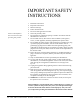
IMPORTANT SAFETY INSTRUCTIONS Please read and follow these instructions before operating this product. 1. 2. 3. 4. 5. 6. 7. 8. 9. 10. 11. 12. 13. 14. 15. Read these instructions. Keep these instructions. Heed all warnings. Follow all instructions. Do not use this apparatus near water. Clean only with dry cloth. Do not block any ventilation openings. Install in accordance with the manufacturer’s instructions.
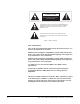
CAUTION RISK OF ELECTRIC SHOCK DO NOT OPEN This symbol alerts you to the presence of uninsulated dangerous voltage within the product's enclosure that might be of sufficient magnitude to constitute a risk of electric shock. Do not open the product's case. This symbol informs you that important operating and maintenance instructions are included in the literature accompanying this product.
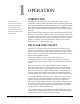
OPERATION Clear-Com is a closed-circuit intercom system that consistently provides high-clarity communication in both high-noise and low-noise environments. INTRODUCTION Congratulations on choosing this Clear-Com product. Clear-Com was established in 1968 and remains the market leader in providing intercoms for entertainment, broadcast and industrial applications. The ruggedness and high build quality of Clear-Com products defines the industry standard.
Visual signal circuitry (call lights), a standard feature on all main and remote stations, allows you to attract the attention of operators who have removed their headsets. The power provided by main stations and power supply units enable remote stations to operate with minimal current while generating extremely loud listen volumes. Depending upon the type of main and remote stations selected and assuming that enough DC power is available remote stations and headset stations can be distributed along 1 mi.
MONITORING SYSTEM The front panel of the CS-702 has one headset connector for use by the operator. The operator monitors the intercom channels by turning up the appropriate listen level volume controls (one for channel A, one for channel B). Either channel may be monitored separately, or both simultaneously (without tying the two channels together). These volume controls are always active regardless of talk channel selection on the station.
SIDETONE The sidetone controls for each channel on the front panel allows adjustment of the operator’s own voice as heard in the headset. LINKING CHANNELS TOGETHER A front panel button is provided. It allows the operator to instantly connect channel A and channel B together for a combined intercom system consisting of both channels. REMOTE MIC-KILL FUNCTION The CS-702 provides the ability to turn off any open mics on remote stations.
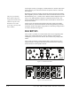
FRONT PANEL DESCRIPTION Normal operation of the CS-702 only requires access to the front panel controls. For intercom operation set the listen level controls for each channel to desired level and press the talk switches when talking. The rest of this section is a detailed description of each control. 12 10 3 5 Channel B Channel A Headset 11 Volume 8 Announce Program Volume Talk Pgm Ch.
channel, turn up the appropriate control. To not listen to a channel, turn the control completely off. 4. Sidetone Controls: Each channel has a sidetone null control. This control is used to set the amount of the microphone that is heard in the earphone from that channel. This control is a true hybrid null control and therefore is sensitive to changes in line loading. For headphone use it is best to find the null for a given channel and then rotate the control clockwise to obtain the desired sidetone level.
The mic and headphone wiring in the headset cord must be individually shielded. Do not connect pins #1 and #3 together. Headset extension cords or headset “Y” cables are not recommended because they will increase crosstalk between channels. 9. Earphone Jack: The jack marked earphone provides an output intended to drive an extra earphone. This output is capable of driving a headphone or loudspeaker. 10.
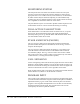
Lowering an excess load or removing a short will allow the automatic reset circuit to attempt to reset the power supply, to restore normal operation to the power supply without operator intervention. REAR PANEL DESCRIPTION 1 5 4 Channel A 6 Relay Out On Off Term Channel B 2 30V, 1.2A Continuous, 2A Peak 3 On Program Input Mic Line Off 3 7 8 Figure 1-4 CS-702 Rear Panel 1. Power Switch: The AC power switch is located on the bottom left corner of the rear panel. 2.
6. Announce Relay Contact Terminals: The announce relay contacts are available on a 1/4” jack. The contact description is as follows: Tip--- C --- Common Ring--- N/C --- Normally Closed Contact Sleeve--- N/O --- Normally Open Contact 7. Program Input Connector: The program input is an XLR-3F. It is an electronically balanced (differential) input. Wiring is as follows: Pin #1 --- Ground Pin #2 --- -Audio Pin #3 --- +Audio 8.
1-10 CS-702 TWO-CHANNEL MAIN STATION
INSTALLATION INSTALLATION OVERVIEW The CS-702 is a combination of a very versatile intercom station and a system power supply. Installations can vary depending on what features are used. The fundamental concept of the Clear-Com party-line intercom is that all stations provide high impedance current sourced signals into a single common system termination. The high DC resistance allows a call voltage to be placed on the line without drawing too much current.
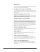
• No power supply. Derives power from the intercom line. • May or may not have terminations. D. POWER SUPPLY: • Supplies system power for external stations. • Provides switch-selectable terminations. SYSTEM POWERING Typical Clear-Com systems consist of a main station and multiple remote stations. The remote stations are powered from the main station through the intercom cable (Figure 2-5).
CABLE CONSIDERATIONS The Clear-Com intercom line is intended to run on a shielded twisted pair of cable per channel of intercom. One conductor carries full duplex (two-way) audio, the other conductor carries the DC power for remote stations. The shield is used for ground return for audio and power. When choosing interconnect cable, keep the following considerations in mind: 1. DC resistance of the ground or common conductor affects crosstalk. For runs longer than 100 ft. (30.
Permanent Installation Cable Vinyl-jacketed shielded pair is the cable of choice for permanent installations. Use a low-capacitance 20-gauge wire for short runs (under 500 ft. [152.5 m]) and 18-gauge cable for runs greater than 500 ft. (152.5 m). Placing the cable in conduit is recommended but not necessary. Multi-pair cable that is individually shielded is acceptable for use in multi-channel systems.
Each jumper has three pins, labeled L, S, and M. A jumper plug is placed over pins L and S, which is the default position for the pins. Moving the jumper plug to place it over the following pin sets reconfigures the station for the following line lengths: 2 • Long Lines. For line lengths in excess of 500 feet (152.5 m), place the jumper plug over pins L and S. This is the default position to which the unit is set when shipped from the factory. • Medium Lines.
INTERCONNECTION SETUP After determining system configuration and channel assignment, pick a location for the CS-702; it can be anywhere as long as it is provided with a source of AC power. 1. Use standard shielded mic cable (refer to the section “Cable Considerations”). Always avoid sharp bends in the cabling; allow at least 3 in. (7.62 cm) behind rack-mount units for cable extending from rear panels. 2. Route all cables from the main station to the remote stations.
Pin #3 --- Headphone common Pin #4 --- Headphone hot Speaker Station 1-Channel Beltpack CH A 1-Channel Beltpack Speaker Station Speaker Station 1-Channel Beltpack 1-Channel Beltpack 1-Channel Beltpack CH B 1-Channel Beltpack Headset Volume 1-Channel Beltpack 1-Channel Beltpack Announce Program Volume Talk Pgm Party LIne Link Pgm Remote Mic Kill Adaptor D.C.
2-8 CS-702 TWO-CHANNEL MAIN STATION
MAINTENANCE INTRODUCTION This chapter provides maintenance information for the station. Caution: These servicing instructions are for use by qualified personnel only. To reduce the risk of electrical shock, do not perform any servicing other than that contained in the operating instructions unless you are qualified to do so.
TROUBLESHOOTING TIPS SYMPTOM System does not operate. Talk lights do not illuminate blue. Red short LED is not illuminated. The red short light stays illuminated. Excessive background noise picked up by microphone. Hum or buzz in system. CAUSE SOLUTION Loss of AC power. Plug unit into dependable AC source. Fuse could be blown. Replace power supply. Shorted or mis-wired intercom cable. Remove cables (one at a time) from main station until faulty line is located.
SYMPTOM System feedback (acoustical) System feedback (electrical) Audio sounds low and distorted; call light stays on. CAUSE SOLUTION Volume too high at one station. Adjust. Two or more speaker stations have mics on simultaneously. Move speaker stations farther away from each other. Turn down volume on one or more speaker stations. Headset mis-wired. Rewire headset connector. Headset laying on table and microphone on. Turn mic off. Headset quality.
3-4 CS-702 TWO-CHANNEL MAIN STATION
TECHNICAL SPECIFICATIONS CS-702 TWO-CHANNEL STATION dBu is an absolute measurement. 0 dBu is referenced to 0.
Program Input - Party Line Program Input - Headset Out Party Line - Headset Out Max Distortion Headset Mic - Party Line Headset Mic - Line Out Program Input - Party Line Program Input - Headset Out Party Line - Headset Out Noise Headset Mic - Party Line Program Input - Party Line Program Mic - Party Line Program Input - Headset Out Program Mic - Headset Out Party Line - Headset Out Max Gain Headset Mic - Party Line Headset Mic - Announce Out Program Input - Party Line Program Mic - Party Line Program
Rear Panel Controls Front Panel Connectors Panel Mic: Headset: Front Panel Controls & Indicators Environmental Dimensions Weight (2) Termination On-Off switches (1) Power switch (1) Program input Mic/Line switch (1) 3.
4-4 CS-702 TWO-CHANNEL MAIN STATION
LIMITED WARRANTY Clear-Com warrants that at the time of purchase, the equipment supplied complies with any specification in the order confirmation when used under normal conditions, and is free from defects in workmanship and materials during the warranty period. Return Material Authorization (RMA) numbers are required for all returns. Both warranty and non-warranty repairs are available.
Instructions for reaching Clear-Com’s User Support Centers are given below. Americas and Asia-Pacific Headquarters California, United States Tel: +1.510.337.6600 Email: CustomerServicesUS@clearcom.com Europe, Middle East, and Africa Headquarters Cambridge, United Kingdom Tel: +44 1223 815000 Email: SalesSupportEMEA@clearcom.com Canada Office Quebec , Canada Tel: +1 (450) 653-9669 China Office Beijing Representative Office Beijing, P.R.
For latest contact information please refer to the Service and Support section at www.clearcom.com. NON-WARRANTY REPAIRS AND RETURNS For items not under warranty, you must obtain an RMA by contacting the User Support Center. Clear-Com representatives will give you instructions and addresses for returning your equipment. You must pay all charges to have the equipment shipped to the support center and returned to you, in addition to the costs of the repair.
Clear-Com, including unreasonable or negligent operation, abuse, accident, failure to follow instructions in the manual, defective or improperly associated equipment, attempts at modification and repair not approved by Clear-Com, and shipping damage. Products with their serial numbers removed or defaced are not covered by this warranty.