
Instruction Manual


7 Tempest®24 00 MasterBelt
The mic detect circuit (dynamic/electret) will indicate dynamic when it sees a load of 600Ω or less. It will indicate an
electret when it sees 1kΩ or greater. Between 600Ω and 1kΩ is not recommended as it may not accurately detect mic type.
Talk Bu on A and B
There are two TALK bu ons on each MasterBelt, one for
channel A and the other for channel B . The Talk bu on
enables the microphone signal for the assigned intercom
channels.
Tempest uses an intelligent latching method for TALK
bu ons. Pressing the TALK bu on momentarily will cause
the TALK bu on to latch. Pressing and holding the TALK
bu on will cause the bu on to act as a momentary switch.
Talk tones can be enabled or disabled per MasterBelt. If
enabled, users will here a tone each me the TALK bu on
is pressed.
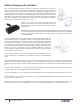
Channel Indicator LEDs A and B
Each Talk bu on has two individual LED indicators. Together they surround the
Talk bu on. The LEDs will fl ash blue to indicate which intercom channel, A or
B , has been selected and will illuminate con nuously to indicate that “Talk” is
enabled on that channel.
The Channel Indicator LEDs will fl ash red when the microphone signal is reaching a peak level and is entering into limi ng.
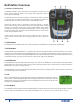
MasterBelt Display Overview
1. Mode Setting - indicates the mode the MasterBelt is currently
opera ng in (NORM, SHARE, or SPLIT.)
2. Battery Alert - indicates that the ba ery alert is enabled or
disabled (shown as enabled).
3. Battery Status - visual indicator of ba ery level.
4. Battery Time - the opera onal me remaining on the ba ery.
5. MasterBelt Name - the name assigned to the MasterBelt.
6. Belt Slot/Status - surrounding box indicates a BeltSta on is
logged into that slot.
7. Channel Indicators - available channels and ac ve channel
shown with surrounding box.
8. Talk Status - TALK is displayed when latched/pressed.
1
2 3
4
5
6
8
7