
User Manual
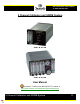


Principles of Operation
5 Channel Calibrator and SGDM System
8
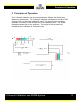
2.2 System Operation
2.2.1 Setup
1) Connect calibration gases to the five ports labeled “CAL GAS IN”
(5).
2) Connect the device to be calibrated (e.g. probe tip) to the port labeled
“CAL GAS OUT - A” (6).
3) Connect the “CAL GAS IN” on the SGDM
(2-11) to the 5 Channel
Calibrator’s “CAL GAS OUT – B”
(6)
NOTE: The “A” and “B” options on the knob denoted the letters above the
“CAL GAS OUT” ports.
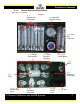
4) Connect the sample line to the “SAMPLE IN” port on the back of the
SGDM
(2-10). The sample gas must be clean and dry before it
reaches this device. In most cases, a gas conditioner will be
necessary to remove moisture.
5) Plug in the devices if you have not already done so.
2.2.2 Calibration
• Probe Tip Calibration
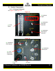
1) Select the desired calibration gas using the calibration gas output
selector knob (3).
2) Using the calibration output selector (4) on the 5 Channel Calibrator,
select “A.”
3) Using the flow meter on the 5 Channel Calibrator (1), adjust the
calibration flow to 1-2 LPM higher than the stack flow rate (in the range
of 1-10 liters per minute).
• Analyzer Calibration
1) Select the desired calibration gas using the calibration gas output
selector knob
(3).
2) Using the calibration output selector (4) on the 5 Channel Calibrator,
select “B.”
3) Press the green “CAL MODE” button on the SGDM (2-4).
NOTE: While in CAL Mode, the SGDM will vent any sample gas.
NOTE: While in CAL Mode, the “CAL MODE” button will be lit.
4) Using the flow meter on the 5 Channel Calibrator
(1), adjust the
calibration flow to the 1-2 LPM higher than the stack flow rate (in the
range of 1-10 liters per minute).
5) Using the SGDM’s flowmeters (2-1) adjust the flow of calibration gas to
the analyzers.