
User Manual

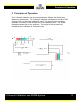

Principles of Operation
5 Channel Calibrator and SGDM System
6
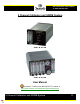
2.1 System Components
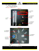
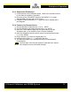
2.1.1 5 Channel Calibrator
See
Figure 1a and Figure 1b.
Figure 1a
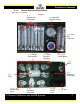
Figure 1b
(2) Indicator
Lights
(3) Calibration
Gas Input
Selection
(4) Calibration
Gas Output
Selection
(1) Flow
Meter
(5) Calibration
Gas Inputs
(6) Calibration
Gas Outputs
(9) 7-Pin
Amphenol
Connection
(7) Power
Cord
(8) Fuse