
Installation Instructions


WWW.CLEANCOMFORT.COM
5
IO-UC36D16-DV
SYSTEM INSTALLATION
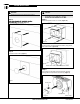
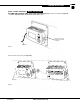
Step 5
Note:
device is installed where the UV light is shining on the
coil or in the cold air return duct.
(Figure 5a)
Figure 5b)
(Figure 5c)
Figure 5a
Figure 5b
Lamp
Figure 5c
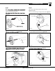
Step 6
Then, insert metal locking clip into holes as shown.
(Figure 6 - A, B, C)
Insert clip under small glass bridge at lamp end. (Figure 6a)
End of clip
Figure 6b
Turn clip end down to lock into place. (Figure 6b)
Locking tab
Twist clip
Figure 6c
Metal
locking clip
Figure 6a
Glass Bridge
(Figure 6c)
Power Module