
Manual

9
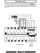
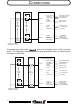
CONNECTIONS
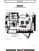
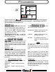
Connections to the vehicle electrical system can be simplified by using the 12 relay
board. Simply install the cab load switches in series between the Total System Manager and
the 12 relay board switch inputs. This installation allows the dash switches to illuminate only
when a load is enabled, giving the operator a quick check of the vehicle’s electrical system
ready status.
25 24 23 22 21 20 19 18 17 16 15 14
MNGT.
POS
NEG
SWITCH 1
SWITCH 2
SWITCH 3
SWITCH 4
SWITCH 5
SWITCH 12
SWITCH 11
SWITCH 10
SWITCH 9
SWITCH 8
SWITCH 7
SWITCH 6
GROUND
PLACE JUMPER IN THE POSITION
OF THE SWITCH’S INPUT POLARITY
PLACE JUMPER IN MNGT POSITION WHEN
USING LOAD MANAGEMENT INPUTS.
1234
56
7891011
1213
N/O 1
N/O 2
N/O 3
N/O 4
N/O 5
N/O 6
12
3
4
5
6
12
11
10 9 8
7
N/O 9
N/O 8
N/O 7
N/O 10
N/O 11
N/O 12
P.N.100714
11/94 RLE
RELAY COILS
1&2
IND
N/C 1
N/C 2
N/C 3
N/C 4
N/C 5
N/C 6
RELAY 1
RELAY 2
RELAY 3
RELAY 4
RELAY 5
RELAY 6
RELAY 7
RELAY 8
RELAY 9
RELAY 10
SW 1
SW 2
SW 3
SW 4
SW 5
SW 6
SW 7
SW 8
SW 9
SW 10
RELAY 11
RELAY 12
SW 11
SW 12
POWER
N/C 11
N/C 12
N/C 10
N/C 9
N/C 8
N/C 7
LOAD MANAGEMENT INPUTS
TOTAL SYSTEM MANAGER
12 RELAY BOARD
Class 1 Inc.
1
2
3
4
5
67
8
910
1112
24 23 22 21
20
19
18 17
16 15 14 13
Load Switches
1 to 12
NO Connection
Set Jumpers
POSITIVE or
NEGATIVE to
match T.S.M.
Outputs.