
Manual

8
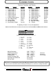
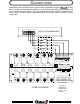
TERMINAL FUNCTION POLARITY
1 Load Manager Enable Ground
2 Output Load # 2 Pos/Gnd
3 Output Load # 4 Pos/Gnd
4 Output Load # 6 Pos/Gnd
5 Output Load # 8 Pos/Gnd
6 Output Load #10 Pos/Gnd
7 Output Load #12 Pos/Gnd
8 Auxiliary Battery Alarm Positive
9 Low Voltage Alarm Ground
10 Master Switch Either
11 No Connection ----------
12 Main Battery Voltage Positive
CONNECTIONS
Mating Connector AMP 770587-1
Socket (Loose Form) AMP 171639-1 16-18 Ga
Socket (Strip Form) AMP 171637-1 16-18 Ga
Crimping Tool AMP 90760-1 Pro-Crimper
Contact Extraction Tool AMP 189727-1
Connector and Socket Kit P.N. 101536
Mating Pigtail P.N. 101538
TERMINAL FUNCTION POLARITY
13 Output Load # 1 Pos/Gnd
14 Output Load # 3 Pos/Gnd
15 Output Load # 5 Pos/Gnd
16 Output Load # 7 Pos/Gnd
17 Output Load # 9 Pos/Gnd
18 Output Load # 11 Pos/Gnd
19 Output Variable Trip Positive
20 Output Fast Idle Positive
21 Parking Brake Either
22 No Connection -----------
23 Input Aux. Battery Positive
24 Ground Ground
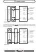
Terminal Function and Polarity
T
HE
BATTERY
PLUS
(
TERM
. #12)
AND
GROUND
(
TERM
. #24 )
SHOULD
BE
WIRED
AS
DIRECT
TO
THE
BATTERY
AS
POSSIBLE
.
These are the connections that the Total System Manager uses to derive it’s voltage information.
1
2
3
4
5
67
8
910
1112
24 23 22 21
20
19
18 17
16 15 14 13
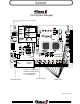
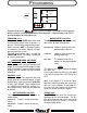
Mating Connector viewed from wire insertion end
1
2
3
4
5
6
7
8
9
10
11
12
13
14
15
16
17
18
19
20
21
22
23
24
Load 1
Load 3
Load 5
Load 7
Load 9
Load 11
Var Trip
Fast Idle
Park Brake
NC
Aux Batt IN
Ground
LM enable
Load 2
Load 4
Load 6
Load 8
Load 10
Load 12
Aux Batt Alarm
Alarm
Master SW
NC
Batt +
JUMPERS J1 AND J2 MUST BE SET TO MATCH THE POLARITY OF THE PARKING BRAKE AND MASTER SWITCH INPUTS.
The polarity of Loads 1-12 are unit dependent.