
Manual

6
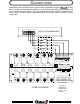
PROGRAMMING
Programming of the Total System Manager is accomplished using push-
button switches and a straightforward menu approach. A digital display and 4 LED’s
provide feedback to the programmer.
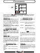
PROGRAM SWITCH
This switch and the USER switch when held
until the display shows three (3) dashes (---)
puts the T.S.M. into the programming mode.
When held until (dEF) is displayed (aprox.
15 seconds), the factory defaults are pro-
grammed into the system.
The final programming step is to hold the
PROGRAM switch until (Pro) is displayed
to save the new values.
PROGRAM MENU SWITCHES
NEXT SWITCH
Pressing this switch will cycle through each
output, the LED next to each output will light
when that output is selected and the digital
display will also indicate the load selected
(L01-L13).
MODE SWITCH AND LED’S
The MODE switch toggles through the avail-
able modes for load management.
RESPONSE LED Output is ON only when the
parking brake IS NOT set.
SCENE LED Output is ON only when the
parking brake IS set.
BOTH LED’S The output can be ON re
gardless of the parking brake
status.
ACTIVE SWITCH AND LED’S
This toggles the switch source for the se-
lected output.
IGNITION LED Output is tied to the ignition
switch.
WRN MASTER Output is tied to the master
switch.
PRIORITY SWITCH
This switch selects the sequence and shed
priority level for the selected output. A small
digital display shows the priorities (P00-P08)
as they cycle through. Loads sequence on
in 1-8 priority and shed off in 8-1 priority. Pri-
ority 0 loads never shed, but will sequence
on and off.
USER
This adjusts the setpoint voltage for output
#13 (term. 19).
Pressing this button increases the ‘trip’ point
in 0.1 volt increments from 10.5 VDC to 15.0
VDC.
NOTE: If the setpoint is 13.8 volts or higher,
output #13 will activate when the system volt-
age rises to the setpoint. If the setpoint is
less than 13.8 volts, output #13 will activate
when the voltage falls to the setpoint.
STORE SWITCH
The STORE switch saves the current con-
figuration for the selected output. The dis-
play will indicate that the values were saved
by showing three (3) dashes (---) and then
the load number (Lxx).
RESPONSE
SCENE
NEXT
STORE
MODE
PRIORITY
USER
DATA
PROGRAM
IGNITION
WRN MASTER
ACTIVE
PROGRAM MENU