CONTENTS CONTENTS ....................................................... 1 STANDARD FEATURES ........................................ 2 LAYOUT ........................................................... 3 OPERATIONAL DATA ....................................... 4-5 PROGRAMMING .............................................. 6-7 CONNECTIONS ............................................. 8-11 DEFAULT SETTINGS ..........................................
STANDARD FEATURES ‘s Total System Manager provides a highly flexible electrical load management system that is user programmable for each output load. þ þ þ þ þ þ þ þ þ þ þ þ þ þ þ þ þ þ þ 2 Main Battery Monitoring Auxiliary Battery Monitoring Electrical Load Shedding Electrical Load Sequencing Reverse Polarity / Short Circuit Protection Sixteen Available Outputs. Priorities can be set for Individual Loads. Each load can be tied to Response and/or Scene Mode.
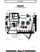
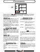
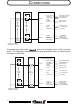
LAYOUT Total System Manager Programming Switches and LED’s PROGRAM MENU RESPONSE NEXT 9 PROGRAM SCENE MODE TP3 +5 STORE IGNITION TP2 GND TP1 VBATT LM ENABLED 10 WRN MASTER ACTIVE OCALA ,FL 4 PRIORITY USER RP4 RP5 RP6 RP7 DATA 11 EVEN SERIES 12 4 3 3 2 2 1 1 13 J1 M J2 P - + POWER LED 2 14 EMM + GMC RSP2 ON OFF OVERIDE POLARITY JUMPERS CN1 J3 SW10 8 7 15 6 5 4 3 1 2 16 AMP Connector 770617-1 Mate 770587-1 Socket 171639-1 Jumpers for Parking Brake a
OPERATIONAL DATA SHED POINTS * Level 0 Never Shed UNSHED POINTS * Level 1 11.4 Volts Level 1 Level 2 Level 3 Level 4 Level 5 Level 6 Level 7 Level 8 Level 2 Level 3 Level 4 Level 5 Level 6 Level 7 Level 8 11.0 Volts 11.4 Volts 11.8 Volts 12.0 Volts 12.2 Volts 12.4 Volts 12.6 Volts 12.7 Volts 11.6 Volts 12.0 Volts 12.2 Volts 12.4 Volts 12.6 Volts 12.8 Volts 13.
OPERATIONAL DATA SWITCH SOURCES OUTPUT MODES Ignition Loads will sequence on when the vehicle ignition switch is turned ON. Response Mode Output is ON only when the Park Brake is NOT set. Warning Master Loads will sequence on when the master warning switch is turned ON. Scene Mode Output is ON only when the Park Brake IS set. Both Output is ON in both Response and Scene Mode. EACH LOAD CAN BE PROGRAMMED FOR ACTIVATION BY EITHER SOURCE USER SETPOINT/VARIABLE TRIP This is the user definable output.
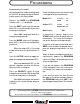
PROGRAMMING PROGRAM MENU RESPONSE NEXT PROGRAM SCENE MODE STORE IGNITION WRN MASTER ACTIVE DATA PRIORITY USER Programming of the Total System Manager is accomplished using pushbutton switches and a straightforward menu approach. A digital display and 4 LED’s provide feedback to the programmer. PROGRAM SWITCH This switch and the USER switch when held until the display shows three (3) dashes (---) puts the T.S.M. into the programming mode. When held until (dEF) is displayed (aprox.
PROGRAMMING Programming Example: You want load #3 to shed at a voltage level of 12.0 VDC, be tied to the Master Switch, and be active in the Scene Mode. Check the display to ensure that the load is configured to your requirements. Mode LED’s Depress the USER and PROGRAM switches until (- - -) is displayed. Active LED’s Press the NEXT switch until the desired load LED is lit and the load that you want to change is displayed. When L03 is displayed, load #3 is ready to be programmed.
CONNECTIONS Terminal Function and Polarity TERMINAL 1 2 3 4 5 6 7 8 9 10 11 12 FUNCTION POLARITY Load Manager Enable Output Load # 2 Output Load # 4 Output Load # 6 Output Load # 8 Output Load #10 Output Load #12 Auxiliary Battery Alarm Low Voltage Alarm Master Switch No Connection Main Battery Voltage TERMINAL Ground Pos/Gnd Pos/Gnd Pos/Gnd Pos/Gnd Pos/Gnd Pos/Gnd Positive Ground Either ---------Positive 13 14 15 16 17 18 19 20 21 22 23 24 FUNCTION POLARITY Output Load # 1 Output Load # 3 Output
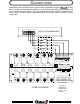
CONNECTIONS Connections to the vehicle electrical system can be simplified by using the 12 relay board. Simply install the cab load switches in series between the Total System Manager and the 12 relay board switch inputs. This installation allows the dash switches to illuminate only when a load is enabled, giving the operator a quick check of the vehicle’s electrical system ready status.
CONNECTIONS CAB SWITCHES LOAD RELAYS Total System Manager LOAD #1 LOAD SWITCH 1 RELAY 1 Master Switch 10 Park Brake 21 Load Manager 1 Enable V.
CONNECTIONS Load Manager Enable T-1 (GND) Display Panel - NEG T-24 POS T-12 + Main Battery Black Ground Red Batt + Yellow Alarm - Brown Fast Idle + POWER ON LOW BATTERY FAST IDLE Cutout size .85" x 1.5" Overall size 1.0" x 1.
DEFAULT SETTINGS The Total System Manager is shipped with the following default settings. PRIORITY 8 7 6 5 4 3 2 1 SHED POINT 12.7 12.6 12.4 12.2 12.0 11.8 11.4 11.0 UNSHED POINT 13.0 12.8 12.6 12.4 12.2 12.0 11.6 11.4 Loads 1 through 8 are set to priority 1 through 8 respectively and are tied to the Master Warning Switch. These loads will sequence on 1 through 8 and sequence off 8 through 1. They will shed 8 through 1 when the system voltage falls to the shed point for that priority level.