
Instruction Manual


FORM-ENG-0018 REV A 05-27-03
607 NW 27th Ave
Ocala, FL 34475
Ph: 352-629-5020 or 1-800-533-3569
Fax : 352-629-2902 or 1-800-520-3473
OPERATION MANUAL
PAGE
14 of 18
DATE 03/01/2013
PRODUCT GROUP System Manager P/N 610-00015 REV 1.01
PRODUCT
Total System Manager
BY GMC
DATASHEET P/N:FSG-MNL-00103 - UNCONTROLLED IN PRINTED FORMAT - PRINTED: 4/2/14
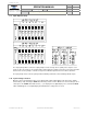
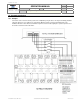
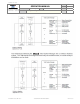
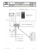
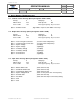
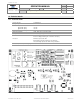
10. Example Installations
10.1. Example.
Connections to the vehicle electrical system can be simplified by using the Class1 12 relay board. Simply install the
cab loads switches in series between the Total System Manager and the 12 relay board switch inputs. This
installation allows the dash switches to illuminate only when a load is enabled, giving the operator a quick check of
the vehicles electrical system ready status.