
Instruction Manual


FORM-ENG-0018 REV A 05-27-03
607 NW 27th Ave
Ocala, FL 34475
Ph: 352-629-5020 or 1-800-533-3569
Fax : 352-629-2902 or 1-800-520-3473
OPERATION MANUAL
PAGE
12 of 18
DATE 03/01/2013
PRODUCT GROUP System Manager P/N 610-00015 REV 1.01
PRODUCT
Total System Manager
BY GMC
DATASHEET P/N:FSG-MNL-00103 - UNCONTROLLED IN PRINTED FORMAT - PRINTED: 4/2/14
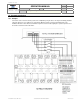
8. Legacy Settings
8.1. History.
The Total System Manager historically was shipped under different part numbers. 101490, 101540, and 101750. The
101490 had positive outputs for loads 1-12 and the 101540 and 101750 had negative outputs for loads 1-12. If
replacing either of these part number use the following setup configurations.
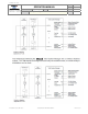
8.2. 101490.
Two configure the unit to work as the 101490 use the following configuration.
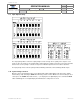
Set the Input polarity shunts to the negative position.
Set the Output polarity switch 1-12 to the positive position.
Set the Output polarity switch A (Low voltage alarm) to the negative position.
Set the Output polarity switch I (Auxiliary Voltage alarm) to the positive position.
Set the Output polarity switch V (Variable Trip) to the positive position.
Set the Output polarity switch HI (High Idle) to the positive position.
Set the system voltage to 12 volts (see section 4.10).
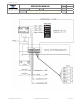
8.3. 101540.
Two configure the unit to work as the 101540 use the following configuration.
Set the Input polarity shunts to the negative position.
Set the Output polarity switch 1-12 to the negative position.
Set the Output polarity switch A (Low voltage alarm) to the negative position.
Set the Output polarity switch I (Auxiliary Voltage alarm) to the positive position.
Set the Output polarity switch V (Variable Trip) to the positive position.
Set the Output polarity switch HI (High Idle) to the positive position.
Set the system voltage to 12 volts (see section 4.10).
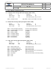
8.4. 101750.
Two configure the unit to work as the 101750 use the following configuration.
Set the Input polarity shunts to the negative position.
Set the Output polarity switch 1-12 to the negative position.
Set the Output polarity switch A (Low voltage alarm) to the negative position.
Set the Output polarity switch I (Auxiliary Voltage alarm) to the positive position.
Set the Output polarity switch V (Variable Trip) to the positive position.
Set the Output polarity switch HI (High Idle) to the positive position.
Set the system voltage to 24 volts (see section 4.10).