
Instruction Manual


FORM-ENG-0018 REV A 05-27-03
607 NW 27th Ave
Ocala, FL 34475
Ph: 352-629-5020 or 1-800-533-3569
Fax : 352-629-2902 or 1-800-520-3473
OPERATION MANUAL
PAGE
11 of 18
DATE 03/01/2013
PRODUCT GROUP System Manager P/N 610-00015 REV 1.01
PRODUCT
Total System Manager
BY GMC
DATASHEET P/N:FSG-MNL-00103 - UNCONTROLLED IN PRINTED FORMAT - PRINTED: 4/2/14
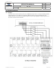
7. Default Settings
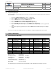
7.1. Defaults.
The Total System manager is shipped with the following default settings.
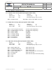
Priority Shed Point UnShed Point
8 12.7 13.0
7 12.6 12.8
6 12.4 12.6
5 12.2 12.4
4 12.0 12.2
3 11.8 12.0
2 11.4 11.6
1 11.0 11.4
Unit is set to work for a 12 volt system
Loads 1 through 8 are set to priority 1 through 8 respectively and are tied to the Master Warning Switch. These loads
will sequence on 1 through 8 and sequence off 8 through 1. They will shed 8 through 1 when the system voltage falls
to the shed point for that priority level.
Loads 9 through 12 are set to priority zero and come on with the ignition switch. These loads will sequence on and off
but will not shed due to voltage.
Load 1 through 12 are configured to BOTH modes SCENE and RESPONSE. The default polarity for outputs 1
through 12 is positive.
Load 13 is the user configurable Output. The default polarity setting output 13 is positive. The default setting for the
'Variable Trip' Point is 14.5 volts.
Load 14 is the AUXILIARY Battery Alarm. The default polarity setting output 14 is positive.
Load 15 is the Fast Idle Output. The default polarity setting for output 15 is positive. This load becomes active when
the system voltage drops to 12.8 volts.
Load 16 is the Low Voltage Alarm Output. The default polarity for output 16 is negative. This load becomes active
when the system voltage drops below 11.9 volts.
The default polarity for the Master Warning Input, Park Brake Input, and Load Manage Enable input is negative.