
Instruction Manual


FORM-ENG-0018 REV A 05-27-03
607 NW 27th Ave
Ocala, FL 34475
Ph: 352-629-5020 or 1-800-533-3569
Fax : 352-629-2902 or 1-800-520-3473
OPERATION MANUAL
PAGE
10 of 18
DATE 03/01/2013
PRODUCT GROUP System Manager P/N 610-00015 REV 1.01
PRODUCT
Total System Manager
BY GMC
DATASHEET P/N:FSG-MNL-00103 - UNCONTROLLED IN PRINTED FORMAT - PRINTED: 4/2/14
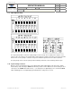
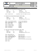
5. Programming Example
5.1. Programming Example
You want load #3 to shed at a voltage level of 12.0 volts. It needs to be tied to the Master Switch and be activated in
the Scene Mode.
1. Depress the USER and PROG switches until (---) is displayed.
2. Press the NEXT switch until L03 is displayed on the digital display.
3. Press the MODE switch until only the SCENE LED is on.
4. Press the ACTIVE switch until only the WRM MASTER LED is on.
5. Press the PRIORITY switch until P04 is displayed on the digital display.
6. Press the STORE switch until 3 dashes (---) are displayed on the digital display.
7. If you want to configure another output select the NEXT switch and repeat the procedure to program that
output.
8. When all the outputs are programmed press and hold PROG switch until Pro is displayed on the digital
display.
Note: If you do not press the STORE switch after each Output is configured that Output will not be changed.
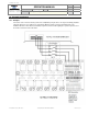
6. Connector Information
6.1. Terminal Function and Polarity
Terminal Function Polarity Terminal Function Polarity
1 Load Manage Enable POS/GND 13 Output Load # 1 POS/GND
2 Output Load # 2 POS/GND 14 Output Load # 3 POS/GND
3 Output Load # 4 POS/GND 15 Output Load # 5 POS/GND
4 Output Load # 6 POS/GND 16 Output Load # 7 POS/GND
5 Output Load # 8 POS/GND 17 Output Load # 9 POS/GND
6 Output Load # 10 POS/GND 18 Output Load # 11 POS/GND
7 Output Load # 12 POS/GND 19 VAR Trip Output POS/GND
8 AUX Battery Alarm POS/GND 20 Output Fast Idle POS/GND
9 Low Voltage Alarm POS/GND 21 Parking Brake Input POS/GND
10 Master Switch Input POS/GND 22 CAN LOW N/A
11 CAN HIGH N/A 23 Aux Battery Input Positive
12 Main Battery Power Positive 24 Ground Ground
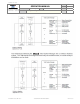
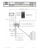
Mating connector AMP 770587-1
Socket(Loose Form) AMP 171639-1 16-18 Ga
Socket(Strip form) AMP 171637-1 16-18 Ga
Crimping Tool AMP 90760-1 Pro Crimper
Contact Extraction Tool AMP 189727-1
Connector and Socket Kit Class1 P.N. 101536
Mating Pigtail Class1 P.N. 101538
The Main battery power (term #12) and ground (term #24) should be wired direct to the battery as possible.