
Instruction Manual

FORM-ENG-0018 REV A 05-27-03
607 NW 27th Ave
Ocala, FL 34475
Ph: 352-629-5020 or 1-800-533-3569
Fax : 352-629-2902 or 1-800-520-3473
OPERATION MANUAL
PAGE
9 of 18
DATE 03/01/2013
PRODUCT GROUP System Manager P/N 610-00015 REV 1.01
PRODUCT
Total System Manager
BY GMC
DATASHEET P/N:FSG-MNL-00103 - UNCONTROLLED IN PRINTED FORMAT - PRINTED: 4/2/14
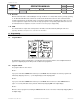
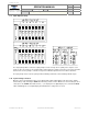
4.9. Input Output Polarity.
The output polarity switches control the output polarity for loads 1 through 16. The polarity of the outputs is set on
power up of the unit. changes to the polarity switches will not take place until the next power cycle. Caution should be
taken to make sure the polarity is selected correctly for the individual output based on the load it is attached to.
The input polarity shunts control the polarity for Master Warning, Park Brake, and Load Manage Enable inputs.
4.10. System Voltage selection.
When the unit is in programming mode press the NEXT switch until the digital display reads either -12 or -24 (the
default setting is -12). Selecting the USER switch will change between -12 or -24. Once the desired setting has been
selected press the STORE switch until 3 dashes (---) are displayed on the digital display. Press and hold the PROG
switch until Pro appears on the digital display this will indicate the setting has been saved.