05216 VERNIER THROTTLE SYSTEM for Caterpillar Electronic Engines Class1 607 NW 27 Ave. Ocala, FL 34475 Ph: (352) 629-5020 Fax: (352) 629-2902 DOC 105216_e:\manuals\throttles\cat\New_CAT_Throt.
Overview Throttle Interface Control Module System Overview The Class1 Vernier Throttle Interface is designed to allow industry standard vernier style controls (such as the Felsted Electronic Vernier II Control) and other potentiometer controls to be used with electronically controlled engines. This unit will work with electronically controlled Caterpillar Engines (C10, C12, 3176, 3406, 3116B and 3126B) using a Pulse Width Modulated (PWM) Signal.
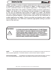
Interlocks Class1 provides a variety of engine controls that are used in a broad range of applications, therefore it is impossible for Class1 to determine the suitability of a particular control for any specific application. The flexibility of our products allows them to be used in a limitless number of custom applications. Class1 can advise you of the features that are available on a given product so that you can determine what product will meet your needs.
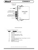
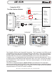
Connector DTM06-12SA Connector Not used Power IN +12 VDC 1 +5 vdc OUT to Vernier 4 Signal IN from Vernier 5 NC 6 NC 7 PWM output to ECM 8 Ground OUT to Vernier 9 High Idle Request IN 10 12 Ground 2 CAN HI 11 CAN LO 3 CAN S 1 4 5 6 7 8 9 10 Caterpillar Control Module 12 Ground Connector Information Connector Deutsh DTM06-12SA Terminal Position 1 2 3 4 5 6 7 8 9 10 11 12 Description 12 VDC Module Power Supply Not Used Not Used Vernier Supply Voltage (+5 VDC) Vernier Analog Signal (0-4.
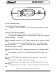
CAT ECM Caterpillar ECM Throttle Interface Module Caterpillar ECM J1 PTO ON/OFF Relay 30 87a 56 87 85 86 Sensor Common (Ground) Fast Idle Interlocks High Idle 10 3 30 Output #1 PTO On Lamp (Ground) PTO ON Lamp Class 1 12 VDC PWM Signal 8 Caterpillar Interface 9 5 4 Ground Signal Source 12 Ground 68 INPUT #8 RAPS PWM A B C Programming Considerations Parameter 8 7 6 5 4 3 2 1 1 2 3 4 CAT ECM J1 Connector Suggested PTO PTO Top Engine Limit PTO RPM set speed PTO Cab Throttle R
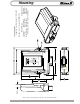
Indicators PWR INP 7 8 9 10 11 12 6 5 4 3 2 1 OUT On Unit Troubleshooting: Is the PWR LED (Red) illuminated? It requires 12 VDC at terminal #1 and Ground at terminal #12 to operate. Is the INP LED (Yellow) Flashing? The flash rate should increase as the vernier is turned out. If the flash rate changes with the vernier position, then the interface is correctly reading the input.
0.63" 2.36" PWR INP OUT PWM SIG GND HI IDLE PN 104997 Phone 352 629 5020 Fax 352 629 2902 http://www.class1.
Operation When the throttle interface module is powered up, it performs a self check and the module then outputs an idle PWM signal of 12 % if the throttle is in the closed position. The interface will verify that the throttle is not open more than half way. If the throttle is open more than half way, the interface module will not increase the PWM until the throttle is closed to less than half way.