
User Manual


7
e:\manuals\throttles\LDSBBT.p65
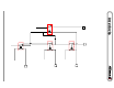
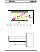
Turn 1 2 3 4 5 6 7
VDC 0.5 1.2 1.9 2.6 3.3 4 4.3
K-ohm 1.55 2.8 4.2 4.9 6.9 7.9 9.4
0.5
1.2
1.9
2.6
3.3
4
4.3
1.55
2.8
4.2
4.9
6.9
7.9
9.4
0
1
2
3
4
5
6
7
8
9
10
1234567
Tur ns
Value
Voltage
Kilohms
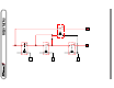
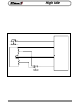
THROTTLE SIGNAL
5 VDC
GROUND
Vernier Throttle
manuals\throttles\GENERIC.ai
Remote Throttle
Switch
OEM Interlocks
Remote Throttle
ON/OFF Switch
Generic Remote Throttle connections f or analog v oltage signal and remote turn on function.
Vernier
Vernier Throttle Voltage/Resistance relationship by full turns . Readings taken from the Blac k
wire (ground) to the Green wire (signal). Regulated 5 VDC is applied to the Red Wire for
V oltage readings. This chart can be used to troubleshoot throttles in the field using the ground
and 5 VDC supply from the engine ECM or Class1 Interface Module. Voltage readings pro-
vide more reliable information than resistance checks. Field readings should be within 5 % of
those shown.
Vernier 101558 readings will be slightly different since it uses a scaled voltage throttle.