
Instruction Manual


3
PTEC II
Hardware
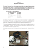
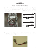
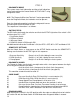
Electronic Control Unit (ECU)
Microprocessor control logic to operate the system. The ECU contains internal memory for
system setup and diagnostic information. Inputs and outputs at the ECU determine system
operation. The ECU should be mounted in an accessible area but protected as much as
possible from physical damage especially the wiring.
P.E.D. # 12047680
P.E.D. # 12040921
1F SYS ACTIVE
3F
2F
MAGGND
5V-OUT
3A
2C
3D
TERM:
CONN:
SOCKET
GROUND
GOV LT
ACTOUT
WIRE
SOCKET
CONN:
TERM:
P.E.D. # 12047680
GOVMODE
PPSI
PSI GND
ACT IN/ON3K
2E
2G
3J
WIRE
INTLK #1A
DIAGNOSTIC
MAGPU
2B
1E
1C
3B INC
1B DEC
P.E.D. # 12034398
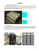
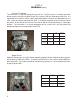
Control Head
This unit contains the switches and LED’s for the user interface to the system. Diagnostics
and System Setup can be performed using the Control Head and a diagnostic connector.
This part of the system is the operator interface and should be mounted on the pump panel at
a height that allows easy operation and viewing.
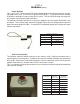
UCE
rotcennoC
-41DHhcstueD
P61-9
lanimreT
-0640hcstueD
14161-202
LANIMRETTEKCOSNOITCNUF
----------A YDAERSYS
F1-2C
BEVITCASYS
E1-1C
CA1#KLTNI
----------
D1#KLTNI
E2-1C
EEDOMVOG
B3-1C
FCNI
B1-1C
GCED
C2-2C
HTLVOG
D3-2C
JDNUORG