
Instruction Manual

14
PTEC II
Notes:
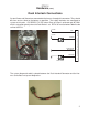
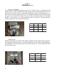
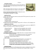
The most common failure in an older system is the transducer circuit. This can be either
wiring, corrosion or a failure in the transducer itself. The common complaint is of no re-
sponse to changing pressures
The second most common failure is with the Park Brake circuit ground. Either a failing
pressure switch or high resistance wiring and connections. It is usually evidenced by
intermittent operation and the engine dropping to Idle unexpectedly.
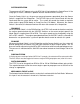
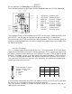
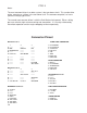
ECU Connector 1 PUMP LIGHT CONNECTOR
1 2 3 A SYS READY
A PLUG PLUG PLUG B SYS ACTIVE
B DEC MAG PU INC C INTLK #1A
C DIAGNOSTIC PLUG PLUG D INTLK #1
D PLUG PLUG PLUG E INC
E INTLK 1A GOV MODE PLUG F DEC
G GOV LGT
F PLUG PLUG PLUG H GROUND
G PLUG PPSI PLUG
H PLUG PLUG PLUG DASH CONNECTOR
J PLUG PLUG PSI GND A BATT +
K PLUG PLUG ACT IN/ON B SYS READY
C DIAGNOSTIC
ECU Connector 2 D GROUND
1 2 3 E INTLK #1
A PLUG PLUG ACT OUT
B PLUG PLUG PLUG
C PLUG GOV LIGHT PLUG ACTUATOR Connector
A PLUG
D PLUG PLUG GROUND B PLUG
E PLUG PLUG PLUG C Ground
F SYS ACTIVE 5V OUT MAG GND D Act Dir A
E Act Dir B
INTERFACE Connector PRESSURE TRANSDUCER
A Act OUT A PSI GND
B PLUG B +5 VDC
C PLUG C PPSI
E GROUND
FBATT + SPEED SENSOR
L INTLK #1A A MAG PU
M ACT IN/ON B MAG GND
N ACT DIR A
P ACT DIR B
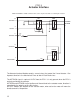
Connector Pinout