
Instruction Manual


13
PTEC II
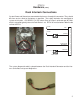
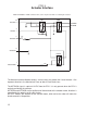
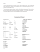
For any operation, the INTERLOCKS must be present.
These can be checked in to the Control Head at A and D and out to the ECM at B and C.
INTLK 1A (WHITE)
SOCKET "C" OUT
SOCKET "D" IN
INTLK 1 (BLUE)
G
ROUND (BLK)
S
OCKET "J" IN
S
OCKET "G" OUT
D
EC (YELLOW)
SYS-READY (GRN)
SOCKET "A" IN
SOCKET "B" OUT
SYS-ACTIVE (YEL)
GOV LT (YELLOW)
SOCKET "H" IN
S
OCKET "F" OUT
NC (BLUE)
SOCKET "E" OUT
GOV MODE (WHT)
RPM
PSI
ON/OFF
MOMENTARY
ON/OFF
ACT RDY
(R) (R) (G) (G)
1
2
4
5
1
2
33
2
6
5
4
A SYS Ready Positive Input
B SYS Active Positive Output
C INTLK 1A Ground Output
D INTLK 1 Ground Input
E GOV Mode Ground Output
F INC Ground Output
G DEC Ground Output
H GOV LT Positive Input
J Ground Ground Input
The interlocks can be visually checked with the LED’s on the panel. If both the READY and
ACTIVE LED’s are ON, then the interlocks are present and the ECU is operational.
Any ground input to the ECU must be below 700 mV potential. The most common source of
erratic or unexpected operation is resistance in the ground interlock circuit, most notably from
the Park Brake Switch.
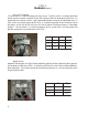
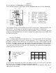
A
C
B
CONN: PACKARD # 12015793
TERM: # 12089305 (PINS)
SOCKET WIRE
A PSI GND
B PPSI
C 5VDC
kcaprehtaeW
lanimreT
noitcnuF
kcapirteM
lanimreT
noitcnuF
ADNGISPA DNGISP
BISPPB CDV5
CCDV5C ISPP
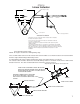
If the transducer voltage goes out of limits low (300 mV) or high (4.85 VDC) the ECU will code
the error (43) for review with the diagnostic connector (page 11).
The most common symptom of a failed transducer will be that the governor “does not re-
spond to pressure changes”.
Pressure Transducer
This is a voltage output device based on pressure. The ECU provides 5 VDC and Signal
Ground to the transducer at terminals B and A respectively. This is a gauge type sensor and
the range is 680 mV at atmospheric pressure (0 Pump PSI) and 4.7 VDC at 300 PSI pump
pressure. The output is linear, so at 150 Pump PSI the output would be 2.7 VDC at terminal
C. There is a Packard Weatherpack 3 pin terminal to connect the transducer to the harness.
The signal and 5 VDC wires are “crossed” at this connector. Use caution when troubleshoot-
ing that you have the correct wires.