PTEC II Pump Throttle Electronic Control Series II PTEC II PN 100509 For Mechanical Diesel Engines 1
PTEC II System Overview The Series II Pressure Governor is a computer controlled throttle and pump interlock monitoring system. The system uses a linear throttle actuator and a set of toggle switches to control engine RPM. It will maintain a selected pump discharge pressure or engine speed in response to the selected mode and desired operating parameter. Pressure sensing is done with a 0-300 PSI transducer and RPM is monitored with a magnetic pick-up.
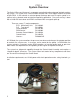
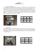
PTEC II Hardware Electronic Control Unit (ECU) Microprocessor control logic to operate the system. The ECU contains internal memory for system setup and diagnostic information. Inputs and outputs at the ECU determine system operation. The ECU should be mounted in an accessible area but protected as much as possible from physical damage especially the wiring. CONN: P.E.D. # 12034398 TERM: P.E.D.
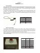
PTEC II Hardware (cont.) Linear Actuator This is a 12 VDC, 2 Amp nominal DC motor incorporating fast braking on direction change, adjustable limits (max. 3 inch) and a high pull force (50 lbs). The resolution of the actuator installation is perhaps the most critical of the system. The least RPM change with the greatest actuator movement possible works best. The actuator should be mounted in an area that subjects it to least amount of vibration, heat and water.
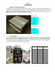
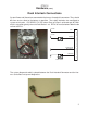
PTEC II Hardware (cont.) Dash Interlock Connections System Power and Ground are connected to the harness through this connector. They should be clean and as direct to the battery as possible. Two safety interlocks are connected to system at this point. SYS READY, 12 VDC when Okay to Pump is achieved and INTLK#1 which is a ground typically when the Park Brake is set. INTLK #1 must be below 700mV to be valid at the ECU.
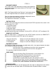
PTEC II Hardware (cont.) Pressure Transducer The transducer is a 300 PSI gauge pressure sensor. The PSI sensor is a voltage generator based on pressure with a range of 4 volts DC starting at 700 mV atmospheric pressure. It is connected to the harness with a 3 pin Packard Metri-pack connector and provided with a 5 VDC source and signal ground by the ECU. It should be mounted on the discharge side of the pump. At the rear of the Pressure Test Port or Master Discharge Gauge is a desirable location.
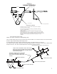
PTEC II Linear Actuator Linkage Assembly 3" Stroke 2" Stroke 1"Stroke Fuel Control Arm Cable Support Bracket Actuator Resolution The further out on the control arm that the actuator cable is installed, the better the actuator resolution. In most cases the fuel control arm needs to be extended to make best use of the 3" actuator stroke. Ideally, a small amount of actuator movement should result in very minor changes in RPM.
WIRE ACTOUT GOV LT GROUND SYS ACTIVE 5V-OUT MAGGND MAGGND PSI GND WIRE ACTOUT GROUND BATT + INTLK #1A ACTINON ACTDIRB ACTDIRA INTERFACE BOX CONN.
PTEC II SYSTEM OPERATION The governor will NOT operate unless the RDY light is illuminated on the Control Panel. If the ready light is not on, it indicates a problem with the interlock circuits or wiring. Once the Ready Light is on, the pressure governor becomes operational when the Govern Switch is toggled to the ON position. The ACTIVE Light on the Control Panel will then be illuminated and the system will be active.
PTEC II DIAGNOSTIC MODE The system stores fault information and these fault indications can be retrieved from the Control Switch ‘ACTIVE LIGHT’ using a diagnostic cable. NOTE: The Diagnostic Wire from Terminal C can be grounded to enter the Diagnostic Mode, the interlocks must be present . Enter the diagnostic mode by installing the diagnostic harness and turning the GOVERN Switch to ON.
PTEC II System Setup ECU SETUP To enter SETUP Mode, place the Diagnostic Connector in-line between the Dash Connector and the Governor Harness.
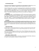
PTEC II Actuator Interface NOTE: ACTINON is 12VDC from ECU and is active only when the ECU is controlling the actuator! M DIR IDLE P ACTDIRA ACTINON J1 ACTDIRB N A ACTOUT J7 F D1 5 AMP IGNITION J5 E GROUND J4 FORCE L PARK BRAKE D2 The Actuator Interface Module contains several relays that control the Linear Actuator. One important function is the Mechanical Force to Idle on Park Brake Loss. The ACTINON signal is a pulsed 12 VDC from the ECU.
PTEC II For any operation, the INTERLOCKS must be present. These can be checked in to the Control Head at A and D and out to the ECM at B and C.
PTEC II Notes: The most common failure in an older system is the transducer circuit. This can be either wiring, corrosion or a failure in the transducer itself. The common complaint is of no response to changing pressures The second most common failure is with the Park Brake circuit ground. Either a failing pressure switch or high resistance wiring and connections. It is usually evidenced by intermittent operation and the engine dropping to Idle unexpectedly.