
Manual

FoamLogix, Model 2.1A and 1.7AHP Class “A”
Electronic Foam Proportioning Systems
93
1
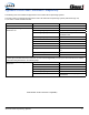
REPAIR KIT 119348 INCLUDES:
2
REQUIRED TOOLS:
- Foam Flow Sensor (200-2481-00-0) - 7/16” wrench (2X)
- Sealing Washer (097-1971-00-0) - 5/16” wrench
- 119376 - Product/Service Bulletin 0017
3
SAFETY INFORMATION
• Remove system power from the FoamLogix system and relieve any trapped pressure.
• Shut off foam tank supply valve.
• Open bypass valve to drain foam lines and use suitable containers to collect residual foam concentrate.
• Protect eyes and skin from foam concentrate per manufacturer’s Material Safety Data Sheet or MSDS.
4
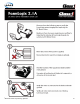
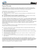
REPLACEMENT INSTRUCTIONS
Remove six nuts
STEPS 3-4
Remove wire harness
STEP 1
Remove hoses
STEP 2
Foam Flow Sensor Replacement Instructions
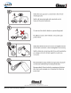
1. Carefully disconnect the wire harness from the old foam ow sensor.
• Connect the NEW foam ow sensor to the wire harness.
• Apply system power and verify sensor diagnostic LED is off.
• Touch end of sensor to brass housing → LED should light.
• Disconnect the wire harness from the new sensor.
• Remove system power from the FoamLogix system.
• (This test veries that the new sensor is operating correctly.)
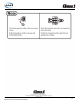
2. Disconnect both hoses from the 3-way bypass valve.
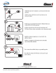
3. Remove the four (4) nuts on the brass owmeter assembly with the two 7/16”
wrenches.
4. Remove the two (2) nuts on the bracket bottom with the 7/16” wrench.
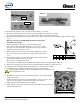
5. Remove the sensor side cover of the owmeter assembly.
• Inspect o-ring inside the cover for damage or cuts.
6. With the 5/16” wrench, loosen the small retaining nut on the foam ow sensor, and
unscrew the sensor by hand.
• Depending on the return instructions provided by the dealer or manufacturer, it may
be necessary to return the old sensor. If not, then the old sensor, nut, and seal washer
can be discarded.
7. The foam ow sensor packaging includes two (2) nuts and two (2) lock washers. Only
one nut is required for the remaining steps.
STEP 6
Sensor nut
& washer
STEP 5