
Manual


FoamLogix, Model 2.1A and 1.7AHP Class “A”
Electronic Foam Proportioning Systems
72
Note: Hale FoamLogix system electronic components
have no user serviceable components inside and are
replaced as a unit.
Opening of Hale FoamLogix electronic
components voids the manufacturer
warranty.
Water
Flow Data
Closed
Loop
System
FoamLogix Control
Display Unit
Foam Flow Data,
A or B Tank
Low Tank Data
Variable Speed
Instructions to
Motor
Water Flo
w
Sensor
Pump/Motor Base
Foam Flow
Data
Foam Flow
Sensor
Distribution
Box
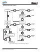
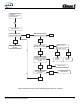
Figure 43: FoamLogix 2.1A & 1.7AHP System Closed-Loop
Flow Diagram
System Overview
See Figure 43: “FoamLogix 2.1A and 1.7AHP
System Closed-Loop Flow Diagram.”
The FoamLogix 2.1A and 1.7AHP are “closed-
loop” systems. The brains behind the system is the
computer-controlled FoamLogix Control Display
Unit. As an electronic system, the ow of data
—”runs“ the system. A basic understanding of how
the system functions makes troubleshooting easier.
Water ow data is fed to the control unit computer.
Since the injection rate (%) is preset, the control
unit calculates the required motor speed of the foam
pump and sends this data to the motor. The output
of the pump is measured by a foam ow feedback
sensor.
The foam ow feedback sensor tells the control
unit how much foam is actually pumped so the
display can make the required motor speed
adjustments. This closed-loop runs several times
per second and is what makes the system so
accurate.
Note: The FoamLogix unit has a “simulated
ow“ function, described in Section 4:
“Operation” heading “Simulated Flow
Operation“ beginning on page 66. This allows
troubleshooting without owing water, yet
simulates an actual water ow.
Distribution Box
The Distribution Box, part of the pump/motor
assembly, sends data on LOW tank warnings tank
selec tion status, as well as foam concen trate ow
feedback to the display.
LOW tank and Tank selection status are also
determined within the distribution box. A connector
at taches to selector valves. This connection signals
the control unit if the unit is in tank selected or ush
mode.
If no accessory is used, a connector plug is installed
to lock the system in the Tank A mode. (See Figure
20: “Control Harness Connections” on page 45.)
Removing this plug or disconnecting the MST
accessory cable places the system in the “ush“
mode.
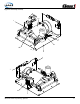
Pump/Motor
The discharge of the foam pump directs foam to
the rotary lobe ow meter.
The rotors are a composite material con taining small
stainless steel targets. As the foam is being pumped,
a target lines up with the sensor in the pump head.