
Manual

FoamLogix, Model 2.1A and 1.7AHP Class “A”
Electronic Foam Proportioning Systems
39
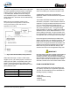
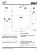
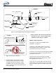
2. The downstream piping length is not as
critical, but there must be a short length
of straight pipe with no ttings or valves
immediately after the ow sensor paddle
wheel. Two to three times the pipe diam eter
is recommended.
37
37
Figure 14: Typical Reduced Size Sensor Piping Arrangement
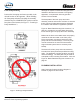
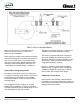
Figure 15: Flow Sensor Placement
3. Do not mount a ow sensor directly after
an elbow or valve. Valves create severe
turbulence when they are “Gated”.
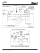
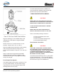
Saddle Clamp Installation
See Figure 16: Flow Sensor/Saddle Clamp
Installation“ on page 40.
Installation of the Paddle Wheel Flow Sensor
using a saddle clamp requires a 1.385“/ 1.390“
(35/35.3mm) bored hole in the pipe.
A minimum of six times the pipe diameter of straight
run pipe without any ttings is neces sary prior to
the position of this hole.
The ow sensor requires a spacer and eight
stainless steel internal hex head screws. These
are supplied with the sensor.
Four 6-32 x 1/2“ screws attach the spacer to the
saddle clamp mount, and four 6-32 x 3/4“ screws
with lock washers attach the paddle wheel to the
spacer.