
Manual

FoamLogix, Model 2.1A and 1.7AHP Class “A”
Electronic Foam Proportioning Systems
31
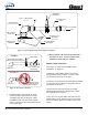
Foam Concentrate Discharge Hose
The system installer must supply ttings and hoses
from the foam pump inject connection to the check
valve/injector tting inlet. All components selected
transfer foam concen trate, therefore they must be
compatible with the foam concentrates being used
in the system.
The foam pump discharge connection is a 1/2” (13
mm) compression tting. The check valve injector
tting connection has 1/2” NPT threads. Hoses and
ttings of 1/2” minimum diameter rated at 500 PSI
(34.5 BAR) work ing pressure or maximum discharge
pressure of the re pump must be used. Fittings and
hoses must be compatible with all foam agents to be
used.
Recommended Components
❑ Hose: Aeroquip 2580-8 or Equivalent
Reinforced Hydraulic Hose.
❑ Fittings: Brass or Stainless Steel Hose End
Crimp or Reusable Type (Aeroquip 412-9-8 or
Equivalent)
Foam Concentrate Bypass Hose
The foam concentrate bypass hose connec tion is
a 1/2” (13mm) hose barb connection. Hoses and
ttings of nominal 1/2” diameter must be used as
bypass hose. Since the bypass hose is used for
calibration and draining the system it does not see
high operating pressures; therefore, a hose with a
lower pressure rating than the inject hose may be
used.
Fittings and hoses used must be compatible
with all foam agents expected to be used. Use
ttings made of brass or 300 series stainless steel
compatible with all foam concentrates.
Recommended Components
❑ Hose: Low Pressure Hydraulic Hose or Air
Brake Tubing
❑ Fittings: Brass or Stainless Steel
It is recommended that the foam concentrate
bypass hose be long enough to extend past the
apparatus running board to reach ve (5) gallon
(19 liter) containers, making foam pump setup and
calibration simpler.
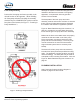
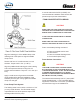
Check Valves
Check valves must be installed on the appa ratus
with foam systems to prevent contami nation of the
foam concentrate with water and contamination
of the fresh water tank with foam. (See Figure 3:
“Typical Hale Foam-Logix 2.1A and 1.7AHP System
Layout” on page 21.)
When a Hale FoamLogix 2.1A and 1.7AHP foam
injection systems and related components are
properly installed the required check valves are
integral parts of the system.
NFPA standards require a check valve in the foam
concentrate injection line at the injection point. The
Hale p/n: 038-1790-00-0 Integral Check Valve/
Injector Fitting, a standard component included with
the Hale FoamLogix 2.1A and 1.7AHP systems and
installed when a manifold kit is ordered, meets these
requirements and threads directly into the foam
injection port on Hale manifolds.
Check valves must be installed in all water piping
locations where foam concentrate could drain
back into pumps or other compo nents of the re
apparatus.
As a minimum one check valve must be installed
where the water piping that supplies foam solution
connects to the re pump discharge. To more
effectively keep foam contamination out of the re
pump and water tank, double check valves are
recommended.