
Manual


FoamLogix, Model 2.1A and 1.7AHP Class “A”
Electronic Foam Proportioning Systems
24
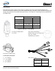
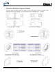
Pipe Size Flow Range
GPM LPM
1.5” 10 - 350 38- 1,219
2” 20 - 550 76 - 2,082
2.5” 30 - 800 114 - 3,028
3” 50 - 1,250 189 - 4,731
4” 75 - 1,800 284 - 6,813
SCV or DCV 30 - 750 114 - 2,839
Figure 4: Pipe Size vs. Flow Range
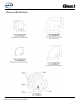
Flow Sensor Weld Fitting
Stainless Steel, p/n: 082-3060-00-0
Steel, p/n: 309020
Aluminium, p/n: 309010
Flow Sensor Paddle Wheel
p/n: 102714
Flow Sensor Saddle Clamp
Threads (NPT) Part Number
2” – p/n: 4842010
2.5” – p/n: 4843010
3” – p/n: 4844010
4” – p/n: 4846010
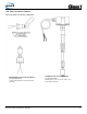
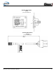
Flow Sensor Cable
Dimension A & B Part Number
10’ x 14’
(3.05m x 4.27m)
113438
15’ x 19’
(4.57m x 5.79m)
113439
B
A
C
D
1'
1'
A
20"
B
Dimension A
Dimension B
Flow Sensors
Each Hale foam system requires a ow sensor for operation. Pipe size must be selected based on the
minimum and maximum water ow in the foam capable discharge. Following is a list of pipe size and rated ow
ranges, along with ow sensor saddle clamp part number. In all in stances, a weld tting may be substituted for
the saddle clamp.