FoamLogix TM Model 2.1A and 1.7AHP Class “A” Electronic Foam Proportioning Systems Description, Installation and Operation Manual HALE PRODUCTS INC. 700 Spring Mill Avenue Conshohocken, PA 19428 Telephone: 610-825-6300 Fax: 610-825-6440 CLASS 1 607 NW 27th Avenue ● Ocala, FL 34475 U.S.A. Telephone: 352-629-5020 FAX: 800-533-3569 GODIVA LTD. Charles Street ● Warwick, England CV34 5LR Phone: 44-1-926-623600 IDEX DINGLEE TECHNOLOGY (Tianjin) Co. Ltd. No.
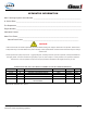
APPARATUS INFORMATION Hale FoamLogix System Serial Number ____________________________________________________ In Service Date ________________________________________________________________________ Fire Department _______________________________________________________________________ Engine Number ________________________________________________________________________ Calibration Factors: Water Flow Factor __________________________________________________________________ Class A Foam Factor ___________
HOW TO USE THIS MANUAL This manual is divided into seven sections for clarity and ease of use. Each of the following manual sections can be a stand alone section or can be used in conjunction with each other. SECTION 1 SAFETY This section must be carefully read, understood and adhered to strictly by all installer/builders, operators and service personnel using the Hale FoamLogix 2.1A and 1.7AHP Foam Proportioning Systems. Do not use or install the system until you have thoroughly read this section.
NOTES FoamLogix, Model 2.1A and 1.
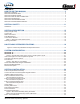
CONTENTS PAGE HOW TO USE THIS MANUAL . .......................................................................................3 SECTION 1 SAFETY..................................................................................................................................... 3 SECTION 2 DESCRIPTION ......................................................................................................................... 3 SECTION 3 INSTALLATION................................................................
Contents -continued ........................................................................ Page SECTION 3 INSTALLATION Continued FOAM PUMP MOUNTING...........................................................................................................34 Figure 7: FoamLogix Pump Installation.................................................................................................. 34 PLUMBING INSTALLATION..........................................................................................
Contents -continued .................................................................... Page START-UP CHECKLIST ................................................................................................48 Electrical......................................................................................................................................................48 Liquid................................................................................................................................
Contents -continued ...................................................................................... Page SECTION 4 OPERATION...........................................................................................................59 Description ................................................................................................................................................ 59 Figure 36: Digital Display Control Unit Overview .............................................................
SECTION 7 ILLUSTRATED PARTS BREAKDOWN ...............................................................76 General . .........................................................................................................................................................76 Abbreviations . ................................................................................................................................................ 76 Foam Pump Assembly............................................................
FoamLogix, Model 2.1A and 1.
SECTION 1 SAFETY IMPORTANT! THE HALE “FOAMLOGIX™” MODELS 2.1A AND 1.7AHP CLASS “A” ELECTRONIC FOAM PROPORTIONING SYSTEMS ARE DESIGNED FOR OPTIMUM SAFETY OF ITS OPERATORS AND TO PROVIDE RELIABLE AND SAFE FOAM CONCENTRATE INJECTION. FOR ADDED PROTECTION AND BEFORE ATTEMPTING INSTALLATION OR OPERATION PLEASE FOLLOW THE SAFETY GUIDELINES LISTED IN THIS SECTION AND ADHERE TO ALL WARNING, DANGER, CAUTION AND IMPORTANT NOTES FOUND WITHIN THIS GUIDE.
❑ All electrical systems have the potential to cause sparks during service. Take care to eliminate explosive or hazardous environments during service and/or repair. ❑ To prevent system damage or electrical shock the main power supply wire is the last connection made to the Hale Foam proportioner distribution box. ❑ Release all pressure then drain all concentrate and water from the system before servicing any of its component parts.
❑ There are no user serviceable parts inside Hale Foam system electrical/electronic components. Opening of the distribution box or control unit voids the warranty. ❑ Use mounting hardware that is compatible with all foam concentrates to be used in the system. Use washers, lock washers and cap screws made of brass or 300 series stainless steel. ❑ When making wire splice connections, make sure they are properly insulated and sealed using an adhesive filled heat shrink tubing.
NOTES FoamLogix, Model 2.1A and 1.
SECTION 2 DESCRIPTION The Hale FoamLogix 2.1A and 1.7AHP Foam Proportioning Systems are completely engineered, factory matched foam proportioning systems that provides reliable, consistent foam concentrate injection for Class “A” foam operations. Hale FoamLogix Foam systems accurately deliver from 0.1% to 10.0% (up to the capacity of the foam pump) foam concentrate through a check valve/ injector fitting, directly into the water discharge stream.
The motor speed is constantly adjusted to maintain the operator selected foam concentrate injection rate. Since the system is flow based, injection rate remains constant regardless of changes in system pressure or the number of discharges that are open (within the limits of the sytem). The maximum rated foam concentrate flow, in gallons per minute, is denoted by the model number.
Package “B” includes dual check valve manifold. Note: If package “A” is selected an additional check valve is required where the foam manifold attaches to the pump discharge for NFPA compliance. 4. The Hale FoamLogix 2.1A and 1.7AHP may also be ordered “a-la-carte” if one of the standard packages does not meet end user requirements.
HALE FOAM SYSTEM SPECIFICATIONS Foam Pump Maximum Foam Concentrate Output Maximum System Operating Pressure Maximum Operating Temperature Pump Motor 2.1A Dual Plunger 2.1 GPM (8 LPM) 250 PSI (17 BAR) 160o F (71o C) 0.44 HP (0.3 Kw), 12 VDC Operating Ampere Draw Maximum Ampere Draw 25 AMPS @ 12 VDC 40 AMPS @ 12 VDC FoamLogix, Model 2.1A and 1.7AHP Class “A” Electronic Foam Proportioning Systems 1.7AHP Dual Plunger 1.7 GPM (6.5 LPM) 400 PSI (27.5 BAR) 160o F (71o C) 0.44 HP (0.
Figure 2: Foam Pump Installation Envelope Dimensions FoamLogix, Model 2.1A and 1.
SYSTEM CONFIGURATION Package A Part Number: (Choose One) FLX21-12-1-10-1 (2.1A 12 Volt) FLX21-24-1-10-1 (2.1A 24 Volt) FLX17-12-1-10-1 (1.7AHP 12 Volt) FLX17-24-1-10-1 (1.
(Supplied by system installer) Double Check Valve Assembly Figure 3: Typical Hale FoamLogix 2.1A and 1.7AHP System Layouts (Also see Figure 20: “Control Harness Connections” on page 45) FoamLogix, Model 2.1A and 1.
Hale FoamLogix 2.1A and 1.7AHP Foam Proportioner Systems All Hale FoamLogix 2.1A and 1.7AHP systems include: Foam Pump/Motor Assembly and Control Unit FoamLogix Base Unit, Foam Pump/Motor Assembly 2.1A - 12V: 115498 2.1A - 24V: 115499 1.7AHP - 12V: 119276 1.7AHP - 24V: 119277 Check Valve/Injector Fitting p/n: 038-1790-00-0 Control Display Unit p/n: 111530 FoamLogix, Model 2.1A and 1.
Low Tank Level Sensor Options One Low Tank Level Sensor is Required Bottom Mount Low Level Tank Sensor p/n: 200-2100-04-0 (1” NPT threaded bushing to mount from outside foam tank.) FoamLogix, Model 2.1A and 1.7AHP Class “A” Electronic Foam Proportioning Systems Top Mount Low Level Tank Sensor p/n: 200-2110-06-0 (Extends from 2-1/2’ to 5’ (0.8 to 1.5 meters) - may be cut shorter if required.
Flow Sensors Each Hale foam system requires a flow sensor for operation. Pipe size must be selected based on the minimum and maximum water flow in the foam capable discharge. Following is a list of pipe size and rated flow ranges, along with flow sensor saddle clamp part number. In all instances, a weld fitting may be substituted for the saddle clamp. Pipe Size 1.5” 2” 2.
p/n 038-1570-08-0 FoamLogix, Model 2.1A and 1.
FoamLogix, Model 2.1A and 1.
Remote Start Option Switch p/n: 513-0330-01-0 Remote Start Option Harness p/n: 513-0680-00-0 (5m) FoamLogix, Model 2.1A and 1.
NOTES FoamLogix, Model 2.1A and 1.
SECTION 3 INSTALLATION To simplify installation selection, one of the two packages described in previous Section 2 should be ordered. While either package provides most of the components required for installation, the following guidelines are offered to assist the system installer with a complete system installation. Carefully review the procedures that follow to ensure the system is properly designed.
❑ Foam suction connections drainage ❑ Proper fill openings, per NFPA requirements. ❑ Tank In addition, a foam tank refill system may be required. See Hale EZFill system for installation requirements. CONTROL UNIT AND INSTRUCTION/ SYSTEM DIAGRAM PLACARD Determine a location on the operator panel of the apparatus for the control unit and instruction/ system diagram placard, if provided. These components must be located at the main pump operator position in close proximity to each other.
Foam Concentrate Discharge Hose The system installer must supply fittings and hoses from the foam pump inject connection to the check valve/injector fitting inlet. All components selected transfer foam concentrate, therefore they must be compatible with the foam concentrates being used in the system. The foam pump discharge connection is a 1/2” (13 mm) compression fitting. The check valve injector fitting connection has 1/2” NPT threads. Hoses and fittings of 1/2” minimum diameter rated at 500 PSI (34.
Separate two check valves by at least 6” to 8” (152 to 203mm) of piping to form a dead zone between the check valves. Individual drain lines should be used on each check valve. The waterway check valves must be rated for 500 PSIG (34.5 BAR) test pressure. Flushing Water Hose If a Hale and USFS approved Class “A” foam concentrate is used, flushing of the Hale FoamLogix 2.1A and 1.7AHP systems is not necessary as long as the system is used periodically.
that power is supplied to the Hale Foam-Logix when the main apparatus electrical system is energized and the pump is in gear. Use of a solenoid with a 150 AMP peak, 85 AMP continuous rating is recommended. Figure 5: “Recommended Relay Wiring Schematic” shows the recommended wiring for this relay. Note: This ensures immediate operation when the operator places the apparatus in PUMP mode, and to prevent battery power drain when the apparatus is not running.
Foam Pump Mounting Position the foam pump and motor assembly in the desired location on the apparatus. When installing the foam pump and motor assembly, the assembly should be kept in a HORIZONTAL position with the base plate on the bottom (See Figure 7: “FoamLogix Pump Installation.”) Although the system is sealed and designed to be resistant to the harsh environment of fire fighting apparatus, a compartment with easy operator access is recommended.
Figure 8: Base Plate Mounting Hole Locations The diagram provides recommended guidelines for the installation of system components that handle water, foam concentrate and foam solution. The sequence in which the plumbing installation is completed depends on your individual installation. Water and Foam Solution Plumbing When installing water and foam solution piping runs, use best industry practices to install this piping. Use a suitable pipe sealing compound at all joints.
Note: When the manifold is installed the drain tap that must be placed in the “down” position and plumbed to an individual drain. When properly mounted, the flow sensor and check valve/injector fitting are on the side of the manifold and one of the drain ports is on the bottom. The flow sensor should point upwards slightly to allow drainage of water and sediment. See Figure 12: “Flow Sensor Tee Position Range,” on page 38.
Installation ISO 9001 CERTIFIED Hale HPF25 Flow Sensor Minimum Length Nipple for 2-1/2” (64mm) Pipe = 12-1/2” (318mm) Check Valve Injector Fitting Hale 115 2-1/2” NPT Flange Hale 2H-98H Elbow Hale Mini Manifold, provides 4 discharge outlets.
Using double check valves, separated by at least 6” to 8” (152 to 203mm) of pipe before the foam injection point, ensures that the pump and tank water remain uncontaminated. Flow Sensor The Hale FoamLogix flow sensor is specially designed to enable quick and easy sensor inspection and maintenance. The flow sensor paddle wheel is installed on a saddle clamp or weld fitting to the foam-capable discharge piping of the apparatus.
It must be reduced to 50 PSI (3.5 BAR). It is recommended to installed a check valve at the pressure tap to prevent contamination. FOAM CONCENTRATE PLUMBING CAUTION! MAKE SURE THE FOAM TANK AND FOAM CON CENTRATE SUCTION HOSES ARE CLEAN BEFORE MAKING FINAL CONNECTION TO FOAM PUMP. FLUSH TANK AND HOSES PRIOR TO MAKING CONNECTIONS. MAKE SURE THE FOAM CONCENTRATE IS GRAVITY FED FROM THE TANK TO THE PUMP.
The hose from the foam tank to the strainer must have adequate wall stiffness to withstand the vacuum of the foam pump while it is operating (23” [584 mm] Hg and 50 PSI [3 BAR], Kuriyama, Kuritec K-3130 or K-7130 series or equal). After the foam pump is mounted on the apparatus, connect the PVC hose provided to the strainer inlet. Install the clear plastic hose from the foam tank outlet to the inlet of the strainer/valve assembly. The inlet is on the valve end.
Bypass Valve Inject Hose Connection (1/2” Compression Fitting) Foam Concentrate Inlet Bypass Hose Connection (1/2” Hose Barb) (1/2” Compression Fitting) Foam Concentrate Shut Off Valve (Shown in OPEN position - rotate 90o to CLOSE) Foam Pump Foam Concentrate Strainer Figure 18: Injection and Bypass Hose Connection The inlet connection of the check valve/ injector fitting uses a 1/2” NPT female thread.
ELECTRICAL INSTALLATION Electrical Connections Complete harness electrical diagrams are provided on page 45 of this manual. Refer to these diagrams for proper installation of each of the electrical components. The Hale FoamLogix system is designed to be installed with a minimum of electrical connections. Cables are provided with each Hale FoamLogix system to make the flow sensor, control unit and motor controller box connections.
Control Unit The control unit mounts in the operator panel of the apparatus. The display is secured with four #8 socket head screws. (See Figure 19 “Control Unit Mounting Dimension” for mounting dimensions). The display requires a 7” (178mm) minimum clearance from the back of the operator panel to allow proper connection of cables. Once the control unit is mounted on the operator panel, attach the 14 pin AMP connector on the cable assembly to the back of the display.
Figure 20: Control Harness Connections (Single Tank System Shown) (Connections required during system installation (Red= Power; 12”/305mm Long, p/n: 513-0270-04-0 Wiring Harness) Connect these two connector ends together Grounding Wires* Figure 21: System Power and Ground Connections (for 113434) FoamLogix, Model 2.1A and 1.
Motor Ground / Primary Power CAUTION! CONNECT THE PRIMARY POSITIVE LEAD FROM THE TERMINAL BLOCK TO THE MASTER SWITCH TERMINAL OR RELAY TERMINAL USING MINIMUM 8 AWG TYPE SGX (SAE J1127), CHEMICAL RESISTANT, BATTERY CABLE AND PROTECT WITH WIRE LOOM. PREVENT CORROSION OF POWER AND GROUND CONNECTIONS BY SEALING THESE CONNECTIONS WITH THE SILICONE SEALANT PROVIDED.
Figure 22: Extra Cable Storage FoamLogix, Model 2.1A and 1.
START-UP CHECKLIST Before energizing the apparatus and Hale FoamLogix system for the first time make sure the following items are checked: ELECTRICAL ❑ Tank level sensor wires connected to distribution box and sealed from moisture. ❑ Tank level sensor functions properly. ❑ Control cable connection at distribution box correct and tight. ❑ Flow sensor cable properly connected. cables and wires are secured and protected from damage during operation.
Installation ISO 9001 CERTIFIED SYSTEM INSTALLER START-UP System Installer Start-up On initial power-up of the Hale FoamLogix system, at the installer facility, the following procedures followed. On initial power-upmust of thebeHale FoamLogix system, at the installer facility, the following procedures must be followed. INITIAL SYSTEM POWER CHECK INITIAL SYSTEM POWER CHECK Watch the display on the control unit as the apparatus electrical system is turned ON.
Installation ISO 9001 CERTIFIED CAUTION ! - continued DO NOT PUMP WATER WITH THE HALE FOAM NOT PUMP WATER THE HALE LOGIX DO FOAM PUMP FOR MOREWITH THAN ONE (1) FOAMLOGIX FOAM PUMP FOR MORE THAN ONE (1) MINUTE. DO NOT ATTEMPT TO CALIBRATE FOAM MINUTE. DO NOT ATTEMPT TO CALIBRATE PUMP FEEDBACK SENSOR WITH OTHER THAN FOAM PUMP FEEDBACK SENSOR WITH OTHER END USER SPECIFIED FOAM CONCEN TRATE. THAN END USER SPECIFIED FOAM CONCENTRATE.
INSTALLATION AND DELIVERY CHECK LIST After the Hale FoamLogix system is installed, use the following check list to verify installation and ensure proper system setup when the apparatus is delivered to the end user. INSTALLATION DATE _______ ______ INITIALS ________ _______ ❑ System properly installed. (Review “Start-Up Check List” on page 48.) _______ ________ ❑ Foam pump operation checked. (Review “System Installer Start-Up” on page 49.) _______ ________ ❑ Foam tank and hoses drained of water.
NOTES FoamLogix, Model 2.1A and 1.
USER CALIBRATION The complete Hale FoamLogix Systems; foam pump and motor assembly, control unit and flow sensor, is tested at the factory before shipping to the installer. If the Hale FoamLogix system is properly installed, further calibration IS NOT necessary until delivery to customer. The system permits easy checking of component calibration to assure accurate operation.
Installation Installation ISO 9001 CERTIFIED ISO 9001 CERTIFIED SELECT DISPLAY SELECT DISPLAY Press and HOLD Press and HOLD Continued to ContinuedHOLD to HOLD Figure 27: Display - Flow Sensor Calibration 27: Display - Flow Sensor Calibration Figure 27: Display - Flow Sensor Calibration FLOW SENSOR CALIBRATION FLOW SENSOR CALIBRATION FLOW SENSOR CALIBRATION Verify flow sensor calibration during NFPA/UL testing Displayed when ofVerify the apparatus andcalibration delivery toduring end user.
Installation ISO 9001 CERTIFIED Installation 3. Press the or button and set the SIMULATED FLOW reading to match the actual flow calculated from the Pitot gauge reading. The SIMULATED default Simulated Flow value is factory set to FLOW 3. Press3.thePress or button set the the or and button andreading set the to SIMULATED FLOW 150 GPM (568 LPM) and, if necessary, may be match thereading actual calculated from the Pitot topump match the actual calculated 4.
Installation Installation ISO 9001 CERTIFIED ISO 9001 CERTIFIED Press and Press and release - the release - the default value is default value is shown shown Press and Press and release - the release - the present value is present value is shown shown Figure 31:Display Display Foam Pump Feedback Calibration Figure 30: Display - Foam Concentrate Injection 31: Display - Foam Pump Feedback Calibration Figure 31: - -Foam Pump Feedback Calibration Figure 30: Display - Foam Concentrate Injection Rate RateFigu
Installation ISO 9001 CERTIFIED Installation ISO 9001 CERTIFIED Start the Hale foam FoamLogix pump by 4. Start the4.Hale FoamLogix pump foam by pressing 4. Start the Hale FoamLogix foam pump by pressing the red ON button. the red ON button. pressing the red ON button.
RELIEF VALVE The pressure relief valve is factory tested and set to 300 PSI (21 BAR). (See Figure 35: “Relief Valve.”) During normal installation and operation, the relief valve does not require adjustment. If adjustment is necessary during field installation, contact Hale Products Inc. at 610-825-6300 for Relief Valve Service information. ENGLISH TO METRIC UNITS The FoamLogix Display offers both English and Metric readouts. The Hale FoamLogix system is calibrated at the factory to U.S.
Operation ISO 9001 CERTIFIED Section 4 Operation SECTION 4 OPERATION DESCRIPTION DESCRIPTION Operation of Hale FoamLogix systems is controlled by the Digital Display Control Unit, provided with four push buttonsof (pads). (See Figuresystems is conOperation Hale FoamLogix 36: “Digital Diaplay Control Unit Overview.”) trolled by the Digital Display Control Unit, provided with four push buttons (pads). (See Figure The Hale system constantly monitors 36:FoamLogix “Digital Diaplay Control Unit Overview.
Operation ISO 9001 CERTIFIED DISPLAY INFORMATION DISPLAY INFORMATION The five digit display on the control unit shows the value of the selected function or provides The five digit display on the control unit shows WARNINGS to the operator as the system is the value of the selected function or provides operating. WARNINGS to the operator as the system is operating. A function is selected by pressing the grey DISPLAY button (i).
The value is in the same unit of measure as the water flow. This totalized value may be reset - see heading “Reset Function”. For example, the display may show 9.5, indicating 9.5 gallons (36 liters) of foam concentrate have been used. (See Figure 37: “Display - Function Modes” on page 60.) Bar Graph The bar graph consists of a ten (10) LED array. When the ON button is pressed the left-most LED lights to indicate the system is ON and ready to inject foam concentrate.
Operation Operation ISO 9001 CERTIFIED ISO 9001 CERTIFIED If theIfON is pressed before refilling the the Messages appearing on the alert alert the the thebutton ON button is pressed before refilling Messages appearing ondisplay the display tank,tank, the system runs runs for 30for seconds operator to adverse conditions that could causecause foamfoam the system 30 seconds operator to adverse conditions thatcause could If the ON button is pressed before refilling the operator to adverse conditions that coul
Operation ISO 9001 CERTIFIED Note: This is not necessarily an indication of Note: This is not necessarily anorindication apparatus battery level condition.of It is only apparatus battery level or condition. It is only an indication of adverse operating conditions. an indication of adverse operating conditions.
ISO 9001 CERTIFIED Operation ISO 9001 CERTIFIED NORMAL OPERATION SUMMARY NORMAL OPERATION SUMMARY NORMAL OPERATION SUMMARY OPERATION OPERATION Energize the system OPERATION Energize the system Energize the system ACTION ACTION Energize apparatus and turn ACTION FoamLogix power switch to ON. Energize apparatus and turn Energize apparatus and FoamLogix power switch to turn FoamLogix powerON. switch to ON.
Operation Operation Operation Operation ISO 9001 CERTIFIED ISO 9001 CERTIFIED ISO 9001 CERTIFIED ISO 9001 CERTIFIED OPERATION OPERATION OPERATION OPERATION OPERATION ACTION DISPLAY ACTION DISPLAY ACTION ACTION DISPLAY ACTION DISPLAY DISPLAY Change injection rate Press Press or and hold for Change injection rate rate oror and hold forfor 22 Change injection Press and hold 2 Change injection rate Press Press or and hold for 2 Change injection rate or and hold for 2 seconds.
Operation ISO 9001 CERTIFIED SIMULATED FLOW OPERATION SIMULATED FLOW OPERATION The Simulated Flow mode of the Hale FoamLogix system allowsFlow operation pump The Simulated mode of of the the foam Hale FoamLogix without discharging water through a foam casystem allows operation of the foam pump without pable discharge or when athe flowca sensor is not discharging water through foam pable discharge orfunctioning. when the flow sensor is not functioning.
1 When the FLOW LED lights, press and release the and buttons at the same time. 2 The display shows S 150 (or other preset default value) and the FLOW LED lights. (See Figure 41: “Display - Simulated Flow Operation” on page 64.) 3 Press the ON button. The left-most LED on the bar graph lights and the foam pump begins running. Foam concentrate flows out of the end of the bypass hose. FoamLogix, Model 2.1A and 1.7AHP Class “A” Electronic Foam Proportioning Systems To End Simulated Flow 1.
NOTES FoamLogix, Model 2.1A and 1.
SECTION 5 MAINTENANCE MAINTENANCE PROCEDURES 1. After each use Inspect wiring, hoses, flow sensors and connections for tightness, corrosion, leaks and. or damage. Refer to Figure 3 on page 21. Flush foam pump if a non-approved foam concentrate is used. Also see appendix A, “Hale Foam concentrate Compatibility” beginning on page 87 for recommended foam concentrates. 2. Monthly Remove and clean the foam strainer screen. Flush as required. 3. Monthly Verify water flow calibration. 4.
o Drain the fire pump, valves and fire pump system accessories. The foam system is now winterized and ready for cold weather duty transport and/or cold weather storage. After transport, prior to the placing the unit in service: • Operate the fire pump and discharge 100gpm (380 LPM) of water from a foam capable apparatus discharge. Be sure to collect the discharge in an area, to be cleaned-up later, to mitigate any environmental impact that the anti-freeze / foam solution may cause.
Troubleshooting ISO 9001 CERTIFIED 6 SECTION TROUBLESHOOTING SECTION 6 TROUBLESHOOTING USER DIAGNOSTICS Once the above conditions are met, proceed to the system troubleshooting section to determine the cause of the malfunction. Power indicator lamps are provided on the ❑ Apparatus electrical system energized Power indicator lamps arefeedback provided sensor. on the The distribution box and on the with power supplied to pump panel and distribution box and on the feedback sensor.
Note: Hale FoamLogix system electronic components components inside and are have no user serviceable replaced as a unit. Opening of Hale FoamLogix electronic components voids the manufacturer warranty.
The sensor “sees” the target and sends this signal to the control display, through the distribution box. An indicator lamp on the sensor “flashes” as the target passes the sensor. Depending on how much foam is being pump determines the flashing speed, which could be so fast that the indicator light actually appears to be constant. Bar Graph The bar graph on the control display unit, indicates the system capacity and is a good troubleshooting tool.
Troubleshooting ISO 9001 CERTIFIED TROUBLESHOOTING CHARTS Is Display Lit? NO Is Power Available at Connector C5? NO PROVIDE POWER NO REPLACE HARNESS NO OPEN FOAM DISCHARGE NO RECONNECT OR REPLACE HARNESS NO RECONNECT WATER FLOW SENSOR YES Remove C1 from display. Check for power at Term/ 1.
Troubleshooting ISO 9001 CERTIFIED Continued Is Foam Concentrate being Injected? 1 Verify Calibration Is Correct Amount of Concentrate Injected? NO Does Unit Run at FULL Speed and Shut-Down? YES YES Proceed with NORMAL Operation Check LED on FeedBack Sensor. Is it ON? NO NO YES Verify Motor is running and rotors are turning Running. Does LED FLASH? YES Is Sensor Adjusted Correctly? Remove Connector. Is Remove Connector.
SECTION 7 ILLUSTRATED PARTS BREAKDOWN GENERAL This section contains drawings and the parts breakdown for the serviceable assemblies, components and most commonly used options for the FoamLogix, Model 2.1A Class “A” Electronic Foam Proportioning System. ABBREVIATIONS The following abbreviations may be used in this IPB: A/R................. As required Cm.................. Centimeters Ext.................. External Fwd................. Forward Ga................... Gauge Grd, Gr............
NOTES FoamLogix, Model 2.1A and 1.
FOAM PUMP ASSEMBLY 1. 114034..................................... 1..................... Motor/Pump Assembly - 2.1A - 12 Volt 114035..................................... 1..................... Motor/Pump Assembly - 2.1A - 24 Volt 119274..................................... 1..................... Motor/Pump Assembly - 1.7AHP - 12 Volt 119275..................................... 1..................... Motor/Pump Assembly - 1.7AHP - 24 Volt A. B. C. D. 2. 3. 4. 5. 6. 7. 8. 110521............................
Figure 45: Foam Pump Assembly 1A 1 3 2 1D 1B 1C 6 8 7 4 5 FoamLogix, Model 2.1A and 1.
115497 FOAM FLOW METER ASSEMBLY 1. 044-1920-01-0......................................... 1.......... Flowmeter Right Cover 2. 044-1920-00-0......................................... 1.......... Flowmeter Left Cover 3. 062-0910-00-0......................................... 1.......... Flowmeter Housing 4. 040-0340-00-0......................................... 2.......... O-ring 2-034 Buna-N 70 Durometer 5. 016-1010-00-0......................................... 2.......... Flowmeter Rotor 6. 064-6390-00-0....
Figure 46: Foam Flow Meter Assembly 17 16 15 11 14 10 2 9 4 13 3 7 5,6 1 4 12 8 11 FoamLogix, Model 2.1A and 1.
FLOW SENSOR COMPONENTS 1. 102714.................................................... Paddlewheel Flow Sensor 2. 4842010................................................... Saddle Clamp 2” with Flowmeter Port 4843010................................................... Saddle Clamp 2.5” with Flowmeter Port 4844010................................................... Saddle Clamp 3” with Flowmeter Port 4846010................................................... Saddle Clamp 4” with Flowmeter Port 4845010..........
Figure 47: Flow Sensor Components 1 2 4 3 7 5 Dual Check Valve Manifold Single Check Valve Manifold 6 8 FoamLogix, Model 2.1A and 1.
Additional Foam Logix Components 1. 2. 3. 4. 5. 6. 7. 8. 111530 038-1790-00-0 101-1630-70-0 200-2110-02-0 200-2110-04-0 200-2110-06-0 513-0330-01-0 513-0680-00-0 FoamLogix Control Head Injector Check Valve FoamLogix Placard Side Mount Low Level Tank Sensor Bottom Mount Low Level Tank Sensor Top Mount Low Level Tank Sensor Remote Control Switch Assembly Remote Control Cable - 16’ (4.88m) Figure 48: Additional FoamLogix Components FoamLogix, Model 2.1A and 1.
ADDITIONAL FOAMLOGIX COMPONENTS Figure 49 Additional FoamLogix Components 8 7 (4.88m) 4 6 5 P/N 200-2100-04-0 (1” NPT (13 mm) threaded bushing to mount from outside foam tank.) FoamLogix, Model 2.1A and 1.7AHP Class “A” Electronic Foam Proportioning Systems Top Mount Low Level Tank Sensor P/N 200-2110-06-0 (Extends from 2-1/2’ to 5’ (0.8 to 1.5 meters) - may be cut shorter if required.
FoamLogix Pump Repair Kit Item # Part Number Qty. Description Kit A...........117495 ..................... 1 ............ Plunger and Seals Kit B 117496 ..................... 1 ............ Valve and Seals Kit C .......... 117497..................... 1 ............ Cam Bearing FoamLogix, Model 2.1A and 1.
Appendix A Hale Foam Concentrate Compatibility The following foam concentrates are approved for use in Hale Foam Proportioning Systems. The Class A foam concentrates are approved for use in all Hale Foam Proportioning systems (Hale FoamLogix 5.0, 3.3, 2.1A and 1.7AHP and Hale V Series. TYPE OF FOAM CONCENTRATE MANUFACTURER NAME Ansul Silvex Class A Foam Concentrate Kidde fire Fighting/Angus Fire Forexpan S (0.1% - 1.
Reference The preceding foam concentrates have been tested by Hale Products in a Hale FoamLogix® system to ensure compatibility with Hale FoamLogix® models 2.1A, 1.7AHP, 3.3 and 5.0 Foam Proportioning Systems. These Chemicals were ran for several hundred hours over several months under nominal conditions to make sure they do not harm the Foam System. This list is solely intended to assist the end user in selection of foam concentrate(s) compatible with a Hale FoamLogix® Model 5.0 and 3.
FoamLogix, Model 2.1A and 1.
FoamLogix, Model 2.1A and 1.
FoamLogix, Model 2.1A and 1.
FoamLogix, Model 2.1A and 1.
Foam Flow Sensor Replacement Instructions 1 2 REPAIR KIT 119348 INCLUDES: - Foam Flow Sensor (200-2481-00-0) - Sealing Washer (097-1971-00-0) REQUIRED TOOLS: - 7/16” wrench (2X) - 5/16” wrench - 119376 - Product/Service Bulletin 0017 3 4 • SAFETY INFORMATION Remove system power from the FoamLogix system and relieve any trapped pressure. • Shut off foam tank supply valve. • Open bypass valve to drain foam lines and use suitable containers to collect residual foam concentrate.
STEPS 8-9 Keep STEP 7 Discard 8. Thread the new foam flow sensor nut onto the sensor about 1/2” (12mm). 9. Thread (do NOT push) the new seal washer onto the foam flow sensor about 1/2” (12mm). • This seal washer should be silver in color, with a black, rubber seal on the inner diameter. 10. Thread the new foam flow sensor into the brass cover by hand, so that the sensor tip is flush with the inside face of the cover. • DO NOT USE LOCTITE OR THREAD SEALANT ON THE FOAM FLOW SENSOR.
Express Warranty EXPRESS WARRANTY: Hale Products, Inc (“Hale”) hereby warrants to the original buyer that products manufactured by it are free of defects in material and workmanship for one (1) year. The “Warranty Period” commences on the date the original buyer takes delivery of the product from the manufacturer. LIMITATIONS: HALE’S obligation is expressly conditioned on the Product being: Subjected to normal use and service.
Hale Products, Incorporated 700 Spring Mill Avenue Conshohocken, PA 19428 Telephone: 610-825-6300 Fax: 610-825-6440 CLASS 1 607 NW 27th Avenue ● Ocala, FL 34475 U.S.A. Telephone: 352-629-5020 FAX: 800-533-3569 GODIVA LTD. Charles Street ● Warwick, England CV34 5LR Phone: 44-1-926-623600 IDEX DINGLEE TECHNOLOGY (Tianjin) Co. Ltd. No.