
User Manual

Service, Maintenance & Troubleshooting ❑
35
EZFill Installer / User Guide, p/n: 029-0020-82-0
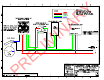
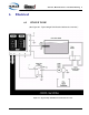
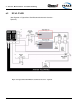
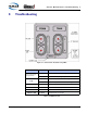
6.3 SPC SMART-SWITCH CONTROLLER
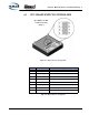
Figure 6-3: SPC Connector Arrangement
Pin No. Circuit Description
1 (S+) Supply + Module Supply (+9VDC....+32VDC
2 (CH) CAN High ES - Key Communications (J1939 CAN)
3 (CL) CAN Low ES - Key Communications (J1939 CAN)
4 (O +) Output Electric Valve Control (Positive, 500mA)
5 (I -) Input Tank Level Switch Input (Ground Polarity)
6 (O +) Output Tank Select Control (Positive 500mA)
7 (O +) Output Foam Fill Pump Control (Positive, 500mA)
8 (S -) Supply Module Supply (Vehicle Ground)
Table 6-4: SPC Connector Assignments
(See Table 6-4: ‘SPC
Connector Assign-
ments.’)