
User Manual

Contents Page
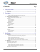
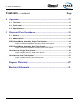
Table of Contents ❑
3
EZFill Installer / User Guide, p/n: 029-0020-82-0
1 Safety Precautions...................................................................................5
1.1 Guidelines............................................................................................................... 5
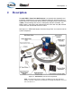
2 Description...............................................................................................7
Figure 2-1:EZFill Refill System Overview, Single Tank .................................................. 7
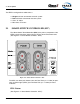
2.1 Smart-Switch Controller (SPC) ............................................................................. 8
Figure 2-2:Smart-Switch Controller - SPC...................................................................... 8
FILL Button........................................................................................................................... 8
Press and Release ......................................................................................................... 9
Press and Release ......................................................................................................... 9
LED Indicators................................................................................................................ 9
FLUSH Button ...................................................................................................................... 9
Press and Release ......................................................................................................... 9
LED Indicators.............................................................................................................. 10
“A” Button ........................................................................................................................... 10
Press and Release ....................................................................................................... 10
LED Indicators.............................................................................................................. 10
“B” Button ........................................................................................................................... 10
Press and Release ....................................................................................................... 10
LED Indicators.............................................................................................................. 10
3 Installation .............................................................................................11
3.1 Plumbing............................................................................................................... 11
Figure 3-1:Three-Position Valve Plumbing, Single Tank.............................................. 11
Figure 3-2:Mounting Bracket Layout ............................................................................ 12
Figure 3-3:Sample, Tank FULL Sensor Mounting ........................................................ 13
Figure 3-4:Quick Disconnect Suction Hose Adapter Installation .................................. 13
3.2 Electrical ............................................................................................................... 14
Smart-Switch Controller (SPC)........................................................................................... 14
Interconnecting Wire Harness............................................................................................ 14
Figure 3-5:Smart-Switch Controller Panel Cutout ....................................................... 15
Figure 3-6:Interconnecting Harness, Single Tank ........................................................ 15
Motor Ground / Primary Power........................................................................................... 16