EZFill Foam Tank Refill System Installer/User Guide Class1 ◆ A Unit of IDEX Corporation 607 NW 27th Avenue ◆ Ocala, FL 34475 U.S.A. Telephone: 352-629-5020 ◆ FAX: 352-629-3569 Web: www.class1.com Hale Products Inc. ◆ A Unit of IDEX Corporation 700 Spring Mill Avenue ◆ Conshohocken, PA 19428 U.S.A. Telephone: 610-825-6300 ◆ FAX: 610-825-6440 Web: www.haleproducts.
NOTICE ! Class1 cannot assume responsibility for product failure resulting from improper maintenance or operation. Class1 is responsible only to the limits stated in the product warranty. Product specifications contained in this manual are subject to change without notice. All Class1 products are quality components -- ruggedly designed, accurately machined, precision inspected, carefully assembled and thoroughly tested.
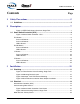
Table of Contents ❑ Contents 1 Page Safety Precautions...................................................................................5 1.1 Guidelines ............................................................................................................... 5 2 Description...............................................................................................7 Figure 2-1:EZFill Refill System Overview, Single Tank .................................................. 7 2.
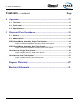
❑ Table of Contents Contents - continued 4 Page Operation ...............................................................................................17 4.1 Tank Full................................................................................................................17 4.2 Flush mode ...........................................................................................................18 4.3 Specifications .................................................................................
Safety Precautions ❑ 1 Safety Precautions IMPORTANT ! THE CLASS1 “EZFILL ” FOAM TANK REFILL SYSTEM IS DESIGNED FOR OPTIMUM SAFETY OF ITS OPERATORS. FOR ADDED PROTECTION AND BEFORE ATTEMPTING INSTALLATION OR OPERATION PLEASE FOLLOW THE SAFETY GUIDELINES LISTED IN THIS SECTION AND ADHERE TO ALL WARNING, DANGER, CAUTION AND IMPORTANT NOTES FOUND WITHIN THIS GUIDE.
❑ Safety Precautions WARNING! NO MODIFICATIONS OR ADDITIONS MAY BE MADE TO the EZFILL FOAM REFILL SYSTEM WITHOUT PRIOR WRITTEN PERMISSION FROM: CLASS 1 A Unit of IDEX Corporation 607 NW 27th Avenue Ocala, FL 34475 U.S.A. Telephone......352-629-5020 FAX ............352-629-3569 Web .......www.Class1.com ❑ Before connecting the wire harness, inspect the seal washers in the female connectors. If a seal washer is missing or damaged, water can enter the connector causing connector pin and terminal corrosion.
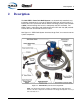
Description ❑ 2 Description The Hale EZFILL Foam Tank Refill System is an electronically controlled, easyto-operate, fixed mount 12 or 24 volt, 5 GPM (19 LPM) foam tank refill system. It features the Class1 push button “Smart-Switch” technology (switch panel controller or SPC), interconnecting wire harness, motor/pump and valve assembly. The EZFill system is self-priming and automatically shuts OFF after sixty (60) seconds or when the foam concentrate reservoir is FULL.
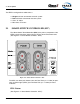
❑ Description The EZFill is configured to handle either a: 2.1 ❑ Single-tank foam concentrate reservoir system ❑ Dual-tank foam concentrate reservoir system ❑ Class “A” and/or ❑ Most Class “B” foams. SMART-SWITCH CONTROLLER (SPC) The “Smart-Switch” Panel Controller (SPC) is the primary component of the EZFill system that allows quick and easy refills of foam concentrate tanks. (See Figure 2-2: ‘Smart-Switch Controller - SPC.
Description ❑ Press and Release The FILL button sets the flush/fill valve to the FILL position. After a few seconds the foam fill pump/motor starts running for sixty (60) seconds or until the tank level FULL sensor is activated. The foam fill pump/motor can be turned OFF at any time by pressing the FILL button again. After the FILL cycle completes, either by activation of the FULL sensor or by pressing the FILL button a second time, the flush/fill valve returns to the FLUSH position.
❑ Description LED Indicators (See Figure 2-2: ‘Smart-Switch Controller - SPC’ on page 8.) ❑ The FLUSH LED is ON while the system is flushing. ❑ The FLUSH LED is OFF when FLUSH is not active. “A” Button Press and Release Sets the electric valve to the TANK “A”’ position (single tank system). Note: In a dual tank system, the tank level select relay is first energized to set the valve to TANK “A.” LED Indicators ❑ The “A” LED is ON steady when foam TANK “A” is selected.
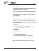
Installation ❑ 3 Installation 3.1 PLUMBING (See Figure 3-1: ‘Three-Position Valve Plumbing, Single Tank.’) Figure 3-1: Three-Position Valve Plumbing, Single Tank IMPORTANT! WHEN DETERMINING THE LOCATION OF THE EZFILL SYSTEM COMPONENTS BEING INSTALLED KEEP IN MIND PIPING RUNS, CABLE ROUTING AND OTHER INTERFERENCES THAT COULD HINDER OR INTERFERE WITH PROPER SYSTEM PERFORMANCE.
❑ Installation Figure 3-2: Mounting Bracket Layout The EZFill may be located in the pump compartment as long as it is protected, preferably mounted “low” for easier pumping and better performance. The EZFill pump/motor assembly must be located where refilling can be easily accomplished with 5 gallon (19 liters) pails or other methods suitable to the end user. The EZFill system is provided with 8.0’ (2.4 meters) of 1” (25.
Installation ❑ Make sure provisions are made for the following plumbing connections: 1. Use only approved sealants on the EZFill refill system. Class1 recommends using: ❑ Plastic Pipe – Permatex #80724 (or equal) thread sealing compound ❑ Metal Pipe – Loctite PST (or equal) thread sealing compound 2. Install the tank FULL level sensor near the top of the appropriate foam tank. (See Figure 3-3: ‘Sample, Tank FULL Sensor Mounting.’) Note: Exact sensor position may vary, depended on tank design. 3.
❑ Installation 6. Connect a hose between the foam tank outlet and the BOTTOM of the foam tank (Tank "A"). (See Figure 3-1: ‘Three-Position Valve Plumbing, Single Tank’ on page 11.) The foam tank fill hose must be plumbed to the bottom of the tank to prevent “foaming” of the concentrate. Notes: The system installer must supply a service shut-off valve at the foam tank. If a “Dual” Tank System is used, a second hose line must be fed from the second 3-position valve to Tank “B.” 7.
Installation ❑ Figure 3-5: Smart-Switch Controller Panel Cutout Figure 3-6: Interconnecting Harness, Single Tank EZFill Installer / User Guide, p/n: 029-0020-82-0 15
❑ Installation If an additional harness extension is required, contact Class1 at 352-629-5020. The power must be fused for 12VDC (or optional 24VDC), minimum 20 amp. circuit to meet NFPA specifications. IMPORTANT ! DO NOT CONNECT POWER SUPPLY HARNESS TO A “LOAD SHEDDING SYSTEM.” Motor Ground / Primary Power CAUTION ! PREVENT CORROSION OF POWER AND GROUND CONNECTIONS BY SEALING THESE CONNECTIONS WITH SILICONE SEALANT.
Operation ❑ 4 Operation The EZFill system should receive its power from the down side of the main disconnect of the apparatus and is always operable while power is supplied to the pump panel. 4.1 TANK FULL 1. When power is supplied to the operator’s control panel, the area around the switches on the smart-switch controller backlights (white) to indicate the system is operational. 2. Connect the suction hose to the quick disconnect adapter on the operator panel and assure a tight seal. 3.
❑ Operation 4.2 FLUSH MODE WARNING! FLUSHING PROCEDURES MUST MEET EPA STANDARDS (AND/OR YOUR DEPARTMENTAL PROCEDURES) IN ACCORDANCE WITH TYPE OF FOAM BEING USED. 1. When power is supplied to the operator’s control panel, the area around the switches on the smart-switch controller backlights (white) to indicate the system is operational. 2. Connect the suction hose to the quick disconnect adapter on the operator panel and assure a tight seal. 3.
Operation ❑ 4.3 SPECIFICATIONS Voltage supply .......................................................................+9 (32VDC) Temperature range ............................................................. -40° to +85°C Maximum continuous current Electric valve control output .................................................... 500mA Tank select control output ....................................................... 500mA Foam fill pump control output..................................................
❑ Operation Notes 20 EZFill Installer / User Guide, p/n: 029-0020-82-0
Illustrated Parts Breakdown 5 Illustrated Parts Breakdown 5.1 GENERAL ❑ This section contains the parts breakdown for the serviceable assemblies, components and most commonly used options for the EZFill Foam Tank Refill System. 5.2 ABBREVIATIONS Kw (kw).... Killowatt Lh, LH...... Left Hand The following abbreviations may be used in this IPB: A/R ...........As required Cm ...........Centimeters Cont. ........Continued Max.......... Maximum Min........... Minimum MM .......... Millimeters Mtg .....
❑ Illustrated Parts Breakdown EZFill Pump/Motor Assembly, Single Tank System Item Part No. Qty. Description 1 ..............010-0940-00-0...................... 1 .............Strainer 2 ..............340-2100-00-0...................... 1 .............Suction Hose Assembly, with 3/4” Stainless Steel Wand 3 ..............112096 ................................. 1 .............Foam Pump/Motor and Valve Assembly 4 ..............200-2110-02-0...................... 1 .............
Illustrated Parts Breakdown ❑ Figure 5-1: EZFill Pump/Motor Assembly, Single Tank System Manual Title, p/n: 029-0020-00-0 23
❑ Illustrated Parts Breakdown EZFill Pump/Motor Assembly, Dual Tank System Item Part No. Qty. Description 1 ..............010-0940-00-0...................... 1 .............Strainer 2 ..............340-2100-00-0...................... 1 .............Suction Hose Assembly, with 3/4” Stainless Steel Wand 3 ..............112096 ................................. 1 .............Foam Pump/Motor and Valve Assembly 4 ..............200-2110-02-0...................... 1 .............
Illustrated Parts Breakdown ❑ Figure 5-2: EZFill Pump/Motor Assembly, Dual Tank System Manual Title, p/n: 029-0020-00-0 25
❑ Illustrated Parts Breakdown Wire Harness, Single Tank System Item Part No. Qty. Description 1 ..............111959 ................................. 1 .............Wire Harness, Single Tank System 2 ..............12193601 ............................. 1 .............Relay, Pump/Motor Run 1 ..............010-0940-00-0...................... 1 .............
Illustrated Parts Breakdown ❑ Wire Harness, Dual Tank System Item Part No. Qty. Description 1 ..............111959 .................................1 .............Wire Harness, Single Tank System 2 ..............12193601 .............................1 .............Relay, Pump/Motor Run 1 ..............010-0940-00-0......................1 .............
❑ Illustrated Parts Breakdown Notes ______________________________________________________________ ______________________________________________________________ ______________________________________________________________ ______________________________________________________________ ______________________________________________________________ ______________________________________________________________ ______________________________________________________________ __________________________________
Limited Warranty EXPRESS WARRANTY EXPRESS WARRANTY: Hale Products, Inc. (HALE) hereby warrants to the original Buyer that products manufactured by Hale are free of defects in material and workmanship for one (1) year. The “Warranty Period” commences on the date the original Buyer takes delivery of the product from the manufacturer. LIMITATIONS: Hale’s obligation is expressly conditioned on the Product being: ● Subjected to normal use and service.
Class1 A Unit of IDEX Corporation 607 NW 27th Avenue Ocala, FL 34475 U.S.A. Telephone................... 352-629-5020 Fax.. ........................... 352-629-3569 Web .......................www.class1.
P E R M I L I A N Y R
EZFill Foam Tank Refill System Service Guide Class1 ◆ A Unit of IDEX Corporation 607 NW 27th Avenue ◆ Ocala, FL 34475 U.S.A. Telephone: 352-629-5020 ◆ FAX: 352-629-3569 Web: www.class1.com Hale Products Inc. ◆ A Unit of IDEX Corporation 700 Spring Mill Avenue ◆ Conshohocken, PA 19428 U.S.A. Telephone: 610-825-6300 ◆ FAX: 610-825-6440 Web: www.haleproducts.
NOTICE ! Class1 cannot assume responsibility for product failure resulting from improper maintenance or operation. Class1 is responsible only to the limits stated in the product warranty. Product specifications contained in this manual are subject to change without notice. All Class1 products are quality components -- ruggedly designed, accurately machined, precision inspected, carefully assembled and thoroughly tested.
Table of Contents ❑ Contents 6 Page Electrical ................................................................................................33 6.1 Single Tank ........................................................................................................... 33 Figure 6-1: Typical Single Tank Electrical Schematic Overview................................... 33 6.2 Dual Tank ..............................................................................................................
❑ Table of Contents Contents - continued Page Notes: _____________________________________________________________ _____________________________________________________________ _____________________________________________________________ _____________________________________________________________ _____________________________________________________________ _____________________________________________________________ _____________________________________________________________ ______________________
Service, Maintenance & Troubleshooting ❑ 6 Electrical 6.1 SINGLE TANK (See Figure 6-1: ‘Typical Single Tank Electrical Schematic Overview.
❑ Service, Maintenance & Troubleshooting 6.2 DUAL TANK (See Figure 6-2: ‘Typical Dual Tank Electrical Schematic Overview Optional.
Service, Maintenance & Troubleshooting ❑ 6.3 SPC SMART-SWITCH CONTROLLER (See Table 6-4: ‘SPC Connector Assignments.’) Figure 6-3: SPC Connector Arrangement Pin No. Circuit Description 1 (S+) Supply + Module Supply (+9VDC....
❑ Service, Maintenance & Troubleshooting 7 Routine Maintenance WARNING! BEFORE BEGINNING ANY INSPECTION OR MAINTENANCE OF THIS EQUIPMENT, VERIFY THAT THE PRESSURE HAS BEEN RELEASED FROM THE SYSTEM. LOCK OUT THE EQUIPMENT IN ACCORDANCE WITH THE MANUFACTURER’S RECOMMENDATIONS AND YOUR DEPARTMENTAL REGULATIONS / PROCEDURES. OPEN THE DISCHARGE VALVES AND REMOVE THE SUCTION TUBE CAPS AND DISCHARGE VALVE CAPS TO RELEASE ANY RESIDUAL PRESSURE. 7.
Service, Maintenance & Troubleshooting ❑ 8 Troubleshooting Figure 8-1: Smart-Switch Troubleshooting LEDs Indicator LED Backlighting Condition Result On SOLID Module is on-line and receiving main power. OFF Module NOT receiving main power CLASS 1 Logo On SOLID Foam FILL pump / motor is running OFF Foam FILL pump / motor is NOT running.
❑ Service, Maintenance & Troubleshooting # 1. Problem EZFill System does not power ON. (Area around switches Does NOT backlight.) Possible Cause Apparatus (operator’s panel) not receiving power. ● Check apparatus operator's panel per manufacturer's recommendations. ● See manufacturer's apparatus manual for troubleshooting procedures. Blown fuse / disconnect (between apparatus and EZFill system). ● Check and replace with same size fuse.
Service, Maintenance & Troubleshooting ❑ # 3. Problem System attempts to FILL and/or FLUSH but no fluid is pumped. Possible Cause KZCO 3-position electric valve not receiving power. Remedy ● Power Check for voltage across power leads to the valve. ● No voltage See preceding Step 1 (on page 38) to verify main power is provided, repair and/or replace accordingly.
❑ Service, Maintenance & Troubleshooting Notes: _____________________________________________________________ _____________________________________________________________ _____________________________________________________________ _____________________________________________________________ _____________________________________________________________ _____________________________________________________________ _____________________________________________________________ _____________________________
Limited Warranty EXPRESS WARRANTY EXPRESS WARRANTY: Hale Products, Inc. (HALE) hereby warrants to the original Buyer that products manufactured by Hale are free of defects in material and workmanship for one (1) year. The “Warranty Period” commences on the date the original Buyer takes delivery of the product from the manufacturer. LIMITATIONS: Hale’s obligation is expressly conditioned on the Product being: ● Subjected to normal use and service.
Class1 A Unit of IDEX Corporation 607 NW 27th Avenue Ocala, FL 34475 U.S.A. Telephone................... 352-629-5020 Fax.. ........................... 352-629-3569 Web .......................www.class1.
P E R M I L I A N Y R