
Manual


5
CONNECTIONS
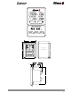
ESC harness connection to the apparatus is achieved by the use of two connectors.
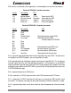
Deutsch DT06-4S 4 socket connector
Cavity Description ESC
A-1 Ignition Power 12V In Power for the ESC
A-2 System Ground Ground in Ground for the ESC
A-3 Data Link + J1587 in Data line positive
A-4 Data Link - J1587 in Data Line negative
Deutsch DT06-12S 12 socket connector
Cavity Description ESC
B-1 Plug
B-2 Plug
B-3 Plug
B-4 Check Engine Ground input from engine ECM
B-5 User Input Ground input from OEM
can be used for STOP ENG
B-6 Plug
B-7 Plug
B-8 Plug
B-9 Alarm Ground output to an OEM alarm
B-10 PTO engaged Positive input for PTO hours
B-11 User Hours Positive input for USER hours
B-12 Low Fuel Ground input for low fuel alert
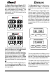
B-4 is a ground input dedicated to the Check Engine Warning of the ESC. To receive this
message on non-DDEC engines, you must provide this input.
B-5 is ground input that will display a generic warning message AUX IN. This can be any
warning signal that you wish the operator to receive. For example on a non-DDEC
engine, provide a ground input from the STOP Engine output of the engine ECM and
change the message to read STOP ENG if you want the Pump Operator to receive the
STOP ENGINE Message.
B-9 is a ground output to an OEM alarm.
B-10 is a positive (12 VDC) input that allows the ESC to accumulate PTO hours.
B-11 is a positive (12 VDC) input that will tally hours as long as the ESC and this input
are active. The display message can be customized by the OEM to indicate its usage.
B-12 is a ground input from a tank level switch to alert the operator of a low fuel condi-
tion.