
User Manual

5
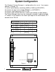
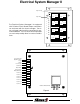
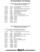
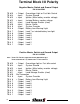
Jumper J1 and J5 are
placed in pos. A.
This provides for seven
load control outputs that
can be sequenced and
shed. These outputs are
at terminals #1 through #7.
The complete terminal de-
scriptions for this mode
are shown in Figure 2,
and one method of wiring
is shown in Figure 3.
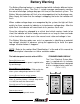
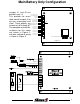
Main Battery Only Configuration
Relay 1
Relay 6
Load
Relays
Dash
Switches
Load SW 1
Load SW 6Load SW 6
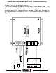
MODE CONFIGURATION
J1
ACBD
J3
J2 J4
Figure 2
Load Level 1
System Override
Load Level 5
Ignition
Load Level 3
Shed Enable
Load Level 7
Over Voltage Lgt/
High Idle Control
Load Level 2
Master Switch
Load Level 6
Ground
Load Level 4
No Connection
Battery Warning Lt
J5
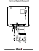
TB #1
TB #9
TB #5
TB #13
TB #3
TB #11
TB #7
TB #15
TB #2
TB #10
TB #6
TB #14
TB #4
TB #12
TB #8
A
B