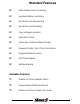
Standard Features Main Battery bank monitoring Isolated Battery monitoring Electrical Load Sequencing Electrical Load Shedding Over Voltage Indication High Idle Control Automatic or Manual Reset Modes Reverse Polarity / Short Circuit Protected Rugged Metal Enclosure LED Status Display Battery Warning Available Features Positive or Ground Master Switch Integral Relay Distribution Board Positive or Ground Output for Loads 1
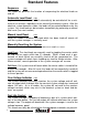
Standard Features Sequence (J3d) This mode will performs the function of sequencing the electrical loads on and off. Automatic Load Reset (J2b) Any load which has been shed will automatically be controlled off for a minimum of five minutes, regardless of the state of the electrical system. After the electrical system becomes stable, the loads will be controlled back on by the system. Any shed load can be turned on immediately by performing a manual load reset (see next section).
Battery Warning The Battery Warning feature is a special output which indicates different states of the electrical system. The Class 1 system manager continuously monitors the rate of discharge (voltage drop per unit time) of the electrical system. The Battery Warning indicator will flash at a rate proportional to the discharge rate. More simply, the faster that the voltage is dropping, the faster the indicator will flash.
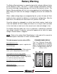
System Configuration The Electrical System Manager is configured by the use of five jumpers labeled J1 through J5. J1 and J5 control battery monitoring (MAIN or MAIN and ISOLATED.) J2 controls the load reset method (MANUAL or AUTOMATIC.) J3 controls Load Sequencing (OFF or ON.) J4 controls when Terminal bar #15 is active (Low Voltage or High Voltage.) The System Manager cover must be removed to change its operating mode.
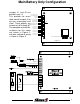
Main Battery Only Configuration Jumper J1 and J5 are Over Voltage Lgt/ placed in pos. A. High Idle Control Ground This provides for seven Ignition load control outputs that No Connection Shed Enable can be sequenced and Master Switch shed. These outputs are System Override Battery Warning Lt at terminals #1 through #7.
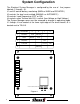
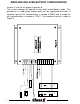
MAIN AND ISOLATED BATTERY CONFIGURATION 6 Figure 5 TB#1 TB#2 TB#3 TB#4 TB#5 TB#6 Dash Switches Load Sw 1 Rly 1 Load Relays TB#8 TB#7 Isolated Batt Lt Rly 6 Master Sw Load Sw 6 connected only when ignition on Battery Warning Lt TB#9 TB#10 TB#11 TB#12 Shed Enable Switch TB#13 TB#14 Isolated Batt Main Batt Ignition Sw Over Voltage Lt TB#15 ELECTRICAL SYSTEM MANAGER Jumper J1 and J5 are placed in position B. The system manager will operate in main and isolated battery mode.
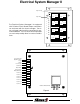
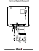
Electrical System Manager II Relay Coil Input 1 5 NO NC NO NC Relay LED©s COM COM 1 6 2 The Electrical System Manager II is equipped with 8 Printed Circuit Board Relays mounted in an enclosure with the load manager. The relay coil input tab should be grounded for normal installations. The common and output tabs on each relay readily allow for custom installations.
Electrical System Manager II 8
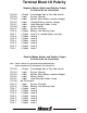
Terminal Block I/O Polarity Negative Master Switch and Positive Output PN 100633 ESM / PN 100756 ESM II TB TB TB TB TB TB TB TB TB TB TB TB TB TB TB #15 #14 #13 #12 #11 #10 # 9 # 8 # 7 # 6 # 5 # 4 # 3 # 2 # 1 + Output - Input + Input + Input - Input - Input + Input + Output + Output + Output + Output + Output + Output + Output + Output Overvoltage light or Fast idle control System Ground Ignition (Main battery monitor voltage) Isolated Battery monitor voltage Load Manage Enable (shed) Master Switch Syst
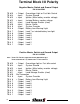
Terminal Block I/O Polarity Negative Master Switch and Ground Output PN 101084 ESM TB TB TB TB TB TB TB TB TB TB TB TB TB TB TB #15 #14 #13 #12 #11 #10 # 9 # 8 # 7 # 6 # 5 # 4 # 3 # 2 # 1 + Output - Input + Input + Input - Input - Input - Input - Output - Output - Output - Output - Output - Output - Output - Output Overvoltage Light or Fast Idle Control System Ground Ignition (Main battery monitor voltage) Isolated Battery monitor voltage Load Manage Enable (shed) Master Switch System Override Battery L
SPECIFICATIONS OPERATING VOLTAGE 7.5 to 20 Volts DC OUTPUTS High Side Drivers Low Side Drivers Vmain @ 0.5 amp (source) Ground @ 0.5 amp (sink) ISOLATED BATTERY INPUT 0 to 20 Volts DC TRANSIENT SUPPRESSION Outputs are protected against thermal overload, direct shorts and transient spikes from -50 to 60 Volts DC. LOAD CONTROL Loads will be cycled on whenever the Master Switch is activated.
SPECIFICATIONS TERMINAL BLOCK #15 This output becomes active for the overvoltage light (high voltage) or for high idle control (low voltage) dependent on the setting of jumper J4. OVER-VOLTAGE INDICATOR Activates at 14.5 VDC and deactivates at 14.0 VDC. HIGH IDLE CONTROL The output will activate when the voltage drops below 12.3 VDC for more than 1 minute. The output will remain ON for a minimum of 5 minutes and until the voltage exceeds 13.0 VDC.
MODELS AND FUNCTIONS Available System Managers and System Manager II’s Terminal Function Block 15 14 13 12 1 0 0 6 3 3 1 0 0 7 5 6 1 0 1 0 8 4 1 0 0 7 6 7 1 0 1 0 3 8 1 0 1 1 1 9 I/O Polarity Over voltage light Output Positive X X X X X X Fast idle control Output Positive X X X X X X System Ground Ignition (main batter y) Isolated batter y Input Ground X X X X X X Input Positive X X X X X X Input Positive X X X Input Positive X X X X X X X X Inpu
SAMPLE CIRCUITS A/C Control Circuit Aux Control Relay Note: As A/C control circuits vary by vehicle, the circuit shown is representative only of one method which can be utilized to interrupt the A/C control circuit. It is the responsibility of the installer to utilize properly rated relays or circuit breakers in the installation. The loading on output #15 should not exceed 0.5 amps.
SAMPLE CIRCUITS TB#15 Relay Fast Idle Switch Ground TB#14 Ignition TB#13 TB#12 Shed Enable TB#11 TB#10 TB#9 TB#8 OEM Fast Idle TB#7 Interlocks TB#6 PSI Switch closed when Park Brake set TB#5 TB#4 OEM Fast Idle Circuit TB#3 TB#2 Relay TB#1 Signal From Brake Lights Automatic FAST IDLE CIRCUIT, disabled when service brake is applied 15