
Manual

18
Aerial Loading
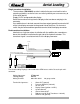
Single transducer installation:
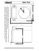
The transducer (PN 102606) must be installed in the pressure feed line to the
actuating cylinder(s) or where it can sense the hydraulic pressure necessary to
lift the aerial device.
Supply 12 VDC and ground to the display.
Route the transducer wiring from the display to the transducer and plug in the
connector.
If an audible alarm is desired, connect the alarm output (ground) from terminal #1
of the 8 pin display connector to the ground side of the alarm. An alarm test
switch may be connected from ground to terminal #8 of the display connector.
Dual transducer installation:
Identical to a single transducer installation with the addition of a second trans-
ducer that should be installed on the rod side of the hydraulic actuator. This
transducer signal is read at terminal #7 of the display connector.
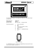
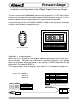
P.N.1800060
WIRE COLOR FUNCTION
1 RED SENSOR SUPPLY
2 WHITE SENSOR SIGNAL
PIN COLOR FUNCTION
1 OEM Alarm OUT (ground)
2 WHITE PRIMARY SIGNAL
3 RED SENSOR SUPPLY
4 RED POWER IN
5 BLACK GROUND IN
6 BLACK NC
7 WHITE SEC. SIGNAL (opt.)
8 OEM Alarm Test (ground)
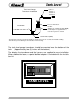
Alarm Output (Ground)
12 VDC
Primary (barrel) Transducer Cable
Alarm Test
Display Power
Secondary (rod) Transducer Cable (OPTIONAL)
Display Ground
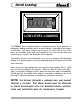
The Aerial Loading Display is connected to the OEM harness with a Deutsch 8 pin mini-
connector.
Mating Connector: DTM06-08S
Locking Wedge WM-8S
Mating Terminal: 0462-201-20141 20 gauge socket
Terminal Assignments: 1 Alarm OUT (ground)
2 Pressure Signal IN (4-20 mA)
3 10 VDC OUT
4 Display Power (Ignition 12 VDC)
5 System Ground
6 Sensor Ground OUT
7 Rod pressure IN (Dual Transducer 4-20 mA)
8 Alarm Test IN (ground)