
Manual

16
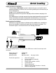
PIN COLOR FUNCTION
A BLACK SENSOR GROUND
B RED SENSOR SUPPLY
C WHITE SENSOR SIGNAL
PIN COLOR FUNCTION
1 PLUG
2 WHITE SIGNAL
3 RED SENSOR SUPPLY
4 RED POWER IN
5 BLACK GROUND IN
6 BLACK SENSOR GROUND
7 PLUG
8 PLUG
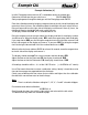
Installation and Operation of the
Class1
Digital Pressure Gauge.
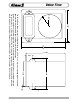
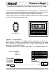
The pressure transducer (PN 102161) mounts to the pump with a 1/4” NPT fitting. Mount
the pressure transducer on the pump discharge manifold and tighten using the 1-1/4 hex.
Mount the digital display on the pump panel using the dimensions provided.
Connect the wiring harness PN 102035, 102060, or 102061 to the transducer, the display
and to the vehicle power and ground circuits.
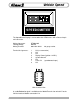
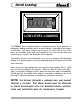
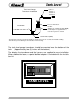
Operation is straightforward.
When the unit is turned on, the display indicates pump pressure at the trans-
ducer location. Normally no calibration is required, however if the gauge
does not read zero when the pump is not running, a ZERO calibration can be
performed. Password L R R L L.
This feature works only on displays that read rP1.7 and above at power on.
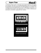
Harness PN 102060 5’
102035 10’
102061 20’
Red +12 VDC
Black Ground
Pressure Gauge
1
2
3
4
8
7
6
5
Wire Insertion View
PUMP DISCHARGE