Contents Table of Contents Contents ................................................................................1 Digital Displays ......................................................................2 Mounting ................................................................................3 Harness .................................................................................4 Cal. Overview .................................................................... 5-6 Flowmeter.........................
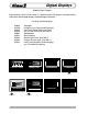
Digital Displays Class1’s Digital Gauges. Digital displays come in both seven (7) segment bright LED displays for alphanumeric information and bargraph displays for percentage information.
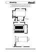
Mounting The Class1 digital display mounts in a 2.85” by 1.55” cutout. Overall area necessary for installation is 2.5” by 3.2”. Two 0.20 diameter holes are provided for mounting screws. 2.840" 1.510 .277 Ø 0.201" (2) HOLES .470 1.900 3.125" 2.462" DIGITAL DISPLAY 0.285" 3.
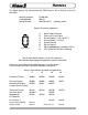
Harness The digital displays are connected to the OEM harness with a Deutsch 8 pin miniconnector.
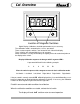
Cal. Overview Location of Magnetic Switches Digital Display Calibration should be performed to assure accuracy. The calibration mode is entered by the use of a “password”. There are two magnetic switches, one located at each side of the display. These switches are activated with the use of a magnet. Switch activation is visually confirmed by the lighting of the closest decimal point on the display to the switch.
Cal. Overview Location of magnetic switches 0 25 50 75 100 BAR GRAPH DISPLAY Display Calibration for Gauges with bargraph displays The calibration mode is entered by the use of a “password”. There are two magnetic switches, one located at each side of the display. These switches are activated with the use of a magnet. Switch activation is visually confirmed by the toggling of the four closest bars on the display to the switch. If they are on they will turn off, if they are off they will turn on.
Flowmeter The Class1 digital flowmeter system comes with the digital display, a paddlewheel transmitter and a connecting harness (specify length). Mounting the transmitter to the discharge can be done with a saddle clamp, a welded boss or a valve adapter. Call for options and specify pipe diameter. The flow display includes a totalizer function. A momentary switch (optional) is required to operate this feature.
Flowmeter Installation The Class1 Digital Flowmeter measures water velocity in the pipe to calculate the flow rate. The location of the paddlewheel transmitter is important for proper operation and accurate readings. Mount the transmitter in a location that is accessible for future maintenance and in an area where laminar (non-turbulent) flow is most likely to be maintained. Most problems with flowmeter accuracy and performance can be traced to the location of the transmitter.
Flowmeter Operation The flowmeter displays the current flow rate whenever the display has power and the discharge is open. Range is 0 to 9995 GPM, LPM or IGPM as calibrated. Totalizer The display includes a totalizer function that displays the total amount of water that has been flowed since the unit was turned on. This feature is enabled by grounding terminal number eight (8) of the display connector. When in the totalizer mode, all decimal points will flash to indicate this mode.
Calibration Calibration Calibration matches the display to the paddlewheel transmitter installation and signal for a given flow rate. A method of accurately determining flow should be used to calibrate the unit. A smoothbore nozzle and a Pitot gauge is suitable. Flowmeter calibration must be performed with the discharge flow stabilized at the desired calibration flow rate. Establish and maintain the calibration flow rate for a minimum of 10 seconds to assure an accurate and stable reading.
Example CAL Example Calibration (4”) Install a Pitot gauge and a two inch (2”) smoothbore nozzle on the deck gun. Determine the flow rate that you want to use. (70 PSI=994 GPM). Start pumping water through the deck gun until the Pitot gauge reads 70 PSI. Enter the calibration mode by bringing a magnet close to the left side of the display and removing it three (3) times, the left decimal point should light with each switch closure.
Value Flow R 1.325" 3.750" 5.000" .683 3.564" 2.750 The Value Series flowmeter uses the digital display and a 2-1/2” or 3-1/2” pressure gauge to give the pump operator information on both flow and pressure for the discharge. A stainless steel bezel is available that can have insets color coded to identify the associated discharge.
Super Flow The flowmeter Super System is designed using the digital flowmeter and the digital pressure gauge. Each piece uses the standard digital display cutout. The only additional consideration from the standard flowmeter is for mounting the pressure transducer. This should generally be mounted after the valve and is a 1/4 NPT fitting. Use only the 1-1/4” hex to tighten the transducer, not the body of the sensor. Follow the calibration procedure for pressure and flow as appropriate after installation.
Vehicle Speed SPEEDOMETER The Speedometer Display is connected to the OEM harness with a Deutsch 8 pin mini-connector.
Vehicle Speed Calibration Digital Speedometer calibration is performed with the vehicle speed stabilized at 40 M.P.H. or (40 K.P.H. ) The calibration mode is entered by the use of a “password”. There are two magnetic switches, one located at each side of the display. These switches are activated with the use of a magnet. Switch activation is visually confirmed by the lighting of the closest decimal point on the display. Enter the switch sequence below to enter calibration mode.
Pressure Gauge Installation and Operation of the Class1 Digital Pressure Gauge. The pressure transducer (PN 102161) mounts to the pump with a 1/4” NPT fitting. Mount the pressure transducer on the pump discharge manifold and tighten using the 1-1/4 hex. Mount the digital display on the pump panel using the dimensions provided. Connect the wiring harness PN 102035, 102060, or 102061 to the transducer, the display and to the vehicle power and ground circuits.
Aerial Loading 0 25 50 75 100 LOW LEVEL LOADING The Class1 Aerial Loading Display is designed to warn aerial operators of dangerous loading conditions when an aerial device is operated at low angles of elevation. Live loads (factors that increase this load such as ice, occupants on the ladder, water load, extra equipment, etc.) are instantly taken into account by the system and displayed to the operator.
Aerial Loading Single transducer installation: The transducer (PN 102606) must be installed in the pressure feed line to the actuating cylinder(s) or where it can sense the hydraulic pressure necessary to lift the aerial device. Supply 12 VDC and ground to the display. Route the transducer wiring from the display to the transducer and plug in the connector. If an audible alarm is desired, connect the alarm output (ground) from terminal #1 of the 8 pin display connector to the ground side of the alarm.
Aerial Loading WARNING: CALIBRATION SHOULD ONLY BE PERFORMED BY THE AERIAL MANUFACTURER! IF YOU FEEL THAT THE DISPLAY NEEDS CALIBRATION, CONTACT YOUR AERIAL MANUFACTURER. Aerial manufacturers must ensure that the lift cylinder(s) do not bottom out during operations. This would cause an erroneous hydraulic pressure reading and the warning system will not operate as designed.
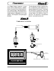
Tank Level Tank Level Gauge Transducer Installation Harness 102193 5' 102194 10' 102195 20' Pressure Transducer 1/4 NPT FLUID TANK Adapter 3/4-1/4 NPT Bushing (OEM) Foam adapter is supplied when a foam level system is ordered. 3/4 NPT Elbow (OEM) The transducer must be mounted vertically as depicted to insure an accurate and reliable reading. This will also prevent damage to the transducer from freezing. The tank level gauge transducer should be mounted near the bottom of the tank.
Tank Level The Tank Level Display is connected to the OEM harness with a Deutsch 8 pin connector.
Tank Level Basic Calibration: (2 point) With the fluid tank empty, enter the calibration password. L L L R R R The left (0%) bar will flash to indicate that you are ready to calibrate for an empty tank. Activate the left switch followed by the right switch. The right (100%) bar will flash to indicate that the display is ready to calculate for a full tank. When the tank is full, actuate the right and then the left switch. Calibration is complete.
Breathing Air 0 25 50 75 100 BREATHING AIR The Class1 Breathing Air Display is designed to provide firefighters with a visible indication of breathing air remaining and an audible warning when there is less than 20% air remaining. The alarm will not activate when there is less than 50 PSI air in the system, this silences the alarm when the air supply is turned off.
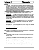
Breathing Air DTM06-08SA 0462-201-20141 20 Ga. 1 2 3 4 5 6 7 8 Alarm OUT (ground) PSI IN (Pressure) Sensor + 10 VDC Power + 12 VDC Ground NC NC Alarm Silence (ground) 0.410" BLACK RED 1.125" 1.425" Wire Insertion View OEM Power Feed 8 7 6 5 1 2 3 4 Alarm OUT PSI Supply PSI Signal Red 12 VDC Black Ground Black Red CONNECTOR Pressure Transducer PROVIDED HARNESS PIN 1 2 COLOR RED BLACK PIN 1 2 3 4 5 6 7 8 COLOR PLUG BLACK RED RED BLACK PLUG PLUG PLUG MANUALS\DIGITAL\AIR_LEFT\AM_HARN.
Breathing Air Calibration for Breathing Air Gauge installations: Empty Cylinder (Closed Valve) With the air bottle closed and the system purged, enter the calibration password. L L L R R R The left (0%) bar will flash to indicate that you are ready to calibrate for an empty system. Activate the left switch followed by the right switch. The right (100%) bar will flash to indicate that the display is ready to calibrate for a full system.
Oxygen Supply 0 25 50 75 100 O2 REMAINING The Class1 Oxygen Remaining Display is designed to provide operators with a visible indication of Oxygen remaining and an audible warning when there is less than 20% oxygen remaining. The audible warning is inactive whenever the pressure is below 50 PSI so that it will not sound when the supply is turned off. The display represents oxygen volume information in an easy to interpret LED bargraph display as a percentage of maximum calibrated pressure.
Oxygen Supply DTM06-08SA 0462-201-20141 20 Ga. 1 2 3 4 5 6 7 8 0.410" Alarm OUT (ground) PSI IN (Pressure) Sensor + 10 VDC Power + 12 VDC Ground NC NC Alarm Silence (ground) BLACK 1.125" RED 1.425" Wire Insertion View OEM Power Feed 8 7 6 5 1 2 3 4 Alarm OUT Red 12 VDC Black Ground PSI Signal PSI Supply Black Red CONNECTOR Pressure Transducer PROVIDED HARNESS PIN 1 2 COLOR RED BLACK PIN 1 2 3 4 5 6 7 8 COLOR PLUG BLACK RED RED BLACK PLUG PLUG PLUG MANUALS\DIGITAL\AIR_LEFT\AM_HARN.
Oxygen Supply Calibration for Breathing Oxygen Gauge installations: Empty Cylinder (Closed Valve) With the oxygen bottle closed and the system purged, enter the calibration password. L L L R R R The left (0%) bar will flash to indicate that you are ready to calibrate for an empty system. Activate the left switch followed by the right switch. The right (100%) bar will flash to indicate that the display is ready to calibrate for a full system.
DUAL OUTPUT CONVERTER Ground Ignition PIN 1 2 3 4 5 6 7 8 COLOR BLACK WHITE BLACK RED BLACK PLUG RED PLUG CIRCUIT SIGNAL 1 SIGNAL 2 XDucer IN V IGN GND -T V+ -- 2.5' 2.5' 5' 2.
3/4 2 2-1/2 U.S.
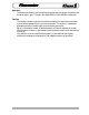
approx 1-5/8" 1-3/4" 1-7/8" 2" 2-1/4" 2-1/2" 3" 6" 358 386 413 437 462 485 506 515 523 530 539 546 555 585 602 620 637 653 669 685 700 715 686 741 792 840 885 928 970 986 1002 1018 1033 1047 1062 1120 1154 1188 1221 1252 1283 1313 1343 1371 4876 5266 5632 5972 6295 6601 6898 7011 7121 7234 7341 7447 7554 7964 8210 8447 8676 8903 9123 9336 9549 9752 415 448 479 508 535 562 587 596 606 615 625 634 643 678 699 719 739 758 776 794 813 830 476 515 550 583 615 644 674 684 695 706 717 728 738 778 802 825 84
LPM Flowchart Flow Calibration Chart PIPE Pitot Kpa Liters per Minute at various nozzle sizes Pressure19mm23.8mm 25.4mm 28.5mm 31.8mm 38.1mm 44.5mm 47.6mm 50.
Notes All of the digital displays have a built in lamp test feature. The password to activate this function is: L L R L L. When activated, all segments on the display LED’s will illuminate for a few seconds and then return to normal operation. The digital displays that utilize a pressure sensor have a sensor check feature. The password to activate this function is: L R R L R R. Special Function Passwords: Transducer Status Check: LRRLRR Pressure Gauge: rP1.
T-shoot DTM06-08SA 0462-201-20141 20 Ga. (ground) Switch Pulses IN Sensor Ground System Ground 8 7 6 5 8 7 6 5 1 2 3 4 1 2 3 4 Alarm OUT (grund) PSI IN Sensor +5/10 VDC System Power Wire Insertion View The display does not illuminate. The display must have power at terminal 4 and ground at terminal 5. With the connector removed, check across pins 4 and 5 for 12 VDC, if 12 volts is present with the correct polarity, replace the display.
T-shoot The tank level gauge has a bar traveling back and forth across the display. There is a problem with the pressure transducer (PN 102162) or wiring. At the transducer connector, check for 5 VDC between pins A (+5 VDC) and pin B (ground). These are sent from the display and must be of the correct polarity for the transducer to function. Plug the connector into the transducer and check for voltage between Pin B (sensor ground) and pin C (sensor signal) at the transducer.