
Owner manual


page 5 of 6 pages
Engineering
Standards
Name Digital Aerial Warning Display
Identifier Installation Information
Engineering Standard Number
C1-102342-A
Calibration for dual and single transducer installations:
Calibration for Gauges with bargraph displays
The calibration mode is entered by the use of a “password”.
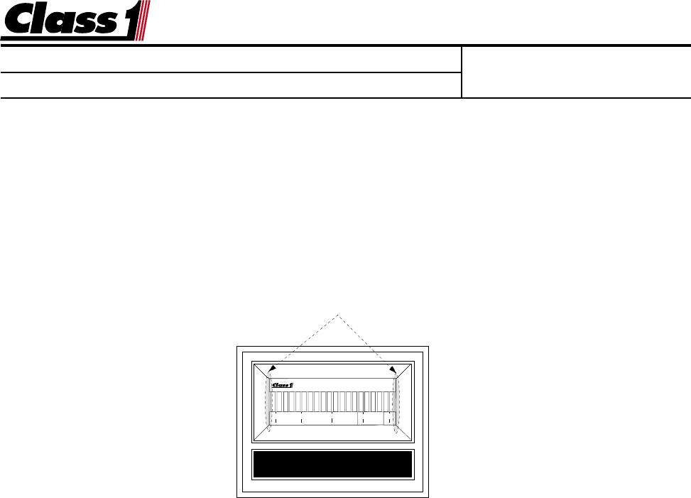
There are two magnetic switches, one located at each side of the display.
These switches are activated with the use of a magnet.
Switch activation is visually confirmed by the toggling of the closest bar on the dis-
play to the switch. If it is on it will turn off, if it is off it will turn on.
MINIMUM LOAD With the ladder retracted, just raised out of the cradle and no load
placed on the device, enter the calibration password.
L L L R R R
The left (0%) bar will flash to indicate that you are ready to calibrate for the minimum
load.
Activate the left switch followed by the right switch.
The right (100%) bar will flash to indicate that the display is ready to calculate for
maximum load.
MAXIMUM LOAD With the ladder extended and maximum load placed at the end of
the aerial device actuate the right switch and then the left switch.
Calibration is complete
NOTE: AERIAL MANUFACTURERS MUST ENSURE THAT THE LIFT CYLINDER(S) DO NOT BOTTOM
OUT
DURING OPERATIONS. THIS WOULD CAUSE AN ERRONEOUS HYDRAULIC PRESSURE READING AND
THE
WARNING SYSTEM WILL NOT OPERATE AS DESIGNED.
BAR GRAPH DISPLAY
0 25 50 75 100
Location of magnetic switches