
Owner manual


page 3 of 6 pages
Engineering
Standards
Name Digital Aerial Warning Display
Identifier Installation Information
Engineering Standard Number
C1-102342-A
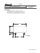
Electrical
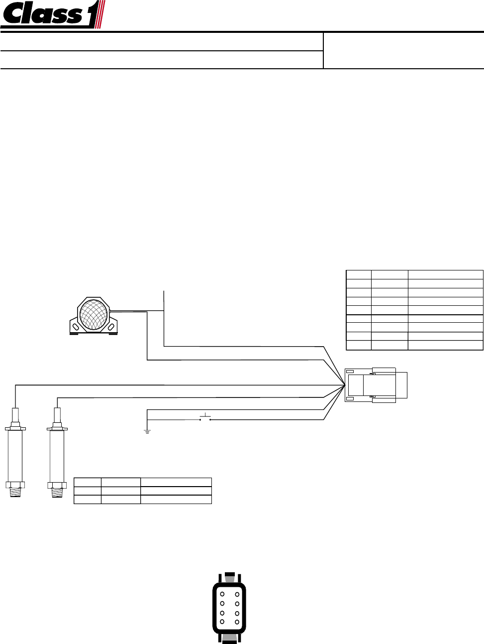
The Aerial Warning Display is connected to the OEM harness with a Deutsch 8 pin
mini-connector.
Mating Connector: DTM06-08S
Locking Wedge WM-8S
Mating Terminal: 0462-201-20141 20 gauge socket
1
2
3
4
8
7
6
5
DTM06-08SA
0462-201-20141 20 Ga.
Wire Insertion View
Switch 8
Pulses IN 7
Sensor Ground 6
System Ground 5
1N/C
2 PSI IN
3 Sensor +5/10 VDC
4 System Power
Mating connector viewed from the wire end
P.N.1800060
WIRE COLOR FUNCTION
1 RED SENSOR SUPPLY
2 WHITE SENSOR SIGNAL
PIN COLOR FUNCTION
1 OEM Alarm OUT (ground)
2 WHITE PRIMARY SIGNAL
3 RED SENSOR SUPPLY
4 RED POWER IN
5 BLACK GROUND IN
6 BLACK NC
7 WHITE SEC. SIGNAL (opt.)
8 OEM Alarm Test (ground)
Alarm Output (Ground)
12 VDC
Primary (barrel) Transducer Cable
Alarm Test
Display Power
Secondary (rod) Transducer Cable (OPTIONAL)
Display Ground