
Instruction Manual


FORM-ENG-0018 REV A 05-27-03
607 NW 27th Ave
Ocala, FL 34475
Ph: 352-629-5020 or 1-800-533-3569
Fax : 352-629-2902 or 1-800-520-3473
TECHNICAL DATA SHEET
PAGE
5 OF 16
DATE 10/1/2010
PRODUCT GROUP
THROTTLE CONTROL
P/N 119971 REV 1.20
PRODUCT
Twister Electronic Throttle (Analog version)
BY AMS
Manual P/N 120478
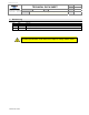
3.2. Throttle ready LED indicator
The green THROTTLE READY LED indicator shows the status of the Twister interlock input (pin 3) and analog signal
diagnostic information.
LED state Throttle control Description
ON PERMITTED Twister interlock input (pin 3) is active.
OFF NOT PERMITTED Twister interlock input (pin 3) is NOT active.
FAST FLASH
(10 Hz)
NOT PERMITTED
Analog signal error (voltage too low).
Verify analog +5 VDC reference and signal line voltage.
DOUBLE BLINK NOT PERMITTED
Analog signal error (voltage too high).
Verify analog ground reference and signal line voltage.
Table 1. Throttle ready LED states.
3.3. Active LED indicator
The blue ACTIVE LED indicator shows the status of the Twister control.
LED state Throttle control Description
ON ACTIVE The twister is in control of engine RPM.
OFF NOT ACTIVE The Twister is not controlling the engine RPM (engine at idle).
FLASHING AT RPM LIMIT
The Twister’s control knob is being rotated while the analog output
signal voltage is already at the configured limit (minimum or
maximum).
Table 2. Active LED states.
3.4. Control knob
The control knob is the operator’s interface for RPM control. The control knob is rotated to change the engine speed
(RPM). The control knob can be configured to increase engine speed with clockwise or counter-clockwise rotation
(section 4.3).
3.5. Idle button
The idle button is the operator’s interface to return the engine’s speed to its idle RPM. Press and hold the idle button
for a half-second to ramp the engine speed to idle and release active engine control from the Twister. The Twister
ramps the output signal down at a rate of 0.9 volts per second.