
Instruction Manual


FORM-ENG-0018 REV A 05-27-03
607 NW 27th Ave
Ocala, FL 34475
Ph: 352-629-5020 or 1-800-533-3569
Fax : 352-629-2902 or 1-800-520-3473
TECHNICAL DATA SHEET
PAGE
14 OF 16
DATE 10/1/2010
PRODUCT GROUP
THROTTLE CONTROL
P/N 119971 REV 1.20
PRODUCT
Twister Electronic Throttle (Analog version)
BY AMS
Manual P/N 120478
6.3. Maintenance
The Twister does not require regular maintenance. The control knob does not require lubrication.
7. Wiring
7.1. Twister connector
The module has one connector and the following definitions apply:
Mating connector: Deutsch DT06-6S GRAY
Mating sockets: Deutsch 0462-201-16141
Gold mating sockets: Deutsch 0462-201-1631
Recommended wire gage: 16-20 AWG
Wedge lock: W6S
PIN CIRCUIT DESCRIPTION
1 SYS POWER (INPUT) – battery voltage (+9VDC…+32VDC)
2 SYS GROUND (INPUT) – battery ground
3 INTERLOCK (INPUT) – Positive/Ground polarity (configurable)
4 SIGNAL REF + (INPUT) – ECM reference voltage, +5 VDC
5 SIGNAL REF - (INPUT) – ECM reference voltage, ground
6 OUTPUT SIG (OUTPUT) – ECM remote throttle control voltage
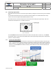
7.2. Twister wiring
Figure 12. Twister harness connections.