
User Manual

FORM-ENG-0018 REV A 05-27-03
PAGE
3 of 22
SUITABLE FOR EXTERNAL DISTRIBUTION
OPERATION MANUAL
DATE 10/23/2007
PRODUCT GROUP ITL P/N 12V: 113739 ; 24V: 114378 REV 1.20
607 NW 27th Ave
Ocala, FL 34475
Ph: 352-629-5020 or 1-800-533-3569
Fax : 352-629-2902 or 1-800-520-3473
PRODUCT
4 LIGHT INTELLI-TANK DISPLAY WITH 1-wire and CAN
BY AMS
DATASHEET P/N:114356 - UNCONTROLLED IN PRINTED FORMAT - PRINTED: 10/24/07
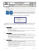
3. Operation
3.1. LED indications
The ITL display uses the 4 LEDs to show the unit status (section 3.1.1), water level (section 3.1.2), and error
conditions (section 3.1.3).
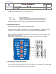
3.1.1. Initial power ON indications
When the display is first powered up the LEDs will cycle on individually starting with the bottom LED (LED 1) and
then the LEDs will show current status.
• A Master display properly connected to a functioning transducer will display current tank level information.
• A Master display not connected to a pressure transducer will alternately flash the bottom two LEDs.
• A Remote display connected to a Master display (through the 1-wire or CAN communication line(s)) will
mimic the Master display’s LED condition and flash pattern.
• A Remote display not connected to a Master display will alternately flash the upper two LEDs and the lower
two LEDs. This indicates a “no communication” condition.
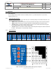
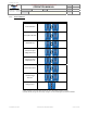
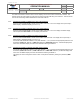
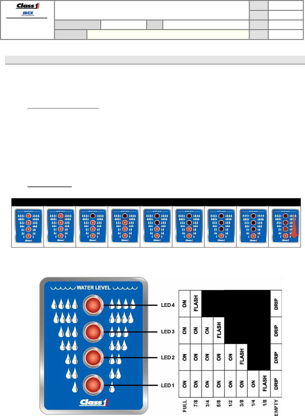
3.1.2. Level indications
FULL 7/8 3/4 5/8 1/2 3/8 1/4 1/8 EMPTY
DRIP = cascades from top (LED 4) to bottom (LED 1), pauses, and repeats.