
User Manual

FORM-ENG-0018 REV A 05-27-03
PAGE
2 of 22
SUITABLE FOR EXTERNAL DISTRIBUTION
OPERATION MANUAL
DATE 10/23/2007
PRODUCT GROUP ITL P/N 12V: 113739 ; 24V: 114378 REV 1.20
607 NW 27th Ave
Ocala, FL 34475
Ph: 352-629-5020 or 1-800-533-3569
Fax : 352-629-2902 or 1-800-520-3473
PRODUCT
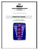
4 LIGHT INTELLI-TANK DISPLAY WITH 1-wire and CAN
BY AMS
DATASHEET P/N:114356 - UNCONTROLLED IN PRINTED FORMAT - PRINTED: 10/24/07
1. Revision Log
Rev Date Approved Changes
1.00 12-12-2005 Initial requirements
1.10 2-26-2007 AK Added CAN harness part numbers
1.20 10-23-2007 AK Added WEEE, CE, and RoHS details
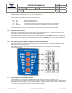
2. System Overview
The Intelli-Tank 4 light tank level (ITL) is designed to display a liquid’s volume to an eighth of a tank level accuracy
through 180-degree viewable ultra-bright LEDs. The unit set as a Master uses a 0 – 5 PSI pressure transducer to
obtain tank level information and then relays that information along the communication line(s) (1-Wire or CAN) to units
set as Remotes. Multiple Remote units can be linked to the Master tank level unit.
2.1. Part numbers
Tank Level Gauge C1 – p/n 113739 – 12V
p/n 114378 – 24V
Labels C1 – p/n 106280 – water
p/n 106281 – foam
p/n 106282 – foam A
p/n 106283 – foam B
Pressure Transducer C1 – p/n 102162 – 0 to 5 PSI gage
Adapter bushing C1 – p/n 102219 – ¾ to ¼ NPT
Installation Harness C1 – p/n 106690 – Master 1-wire
p/n 106691 – Remote 1-wire
p/n 116032-10 – Master CAN, 10 feet length
p/n 116032-20 – Master CAN, 20 feet length
p/n 116032-30 – Master CAN, 30 feet length
p/n 116032-40 – Master CAN, 40 feet length
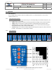
Terminating resistor (CAN) C1 – p/n DT06-3S-P006
“Y” connector (CAN) C1 – p/n DT04-3P-P007
Operation Manual C1 – p/n 114356
2.2. Modes of Operation
Master When the ITL display is calibrated with a proper pressure signal it automatically becomes a Master display
and will send tank level information along the communication line(s) (either 1-wire or CAN) to all other
Remote displays.
Remote ITL displays are initially shipped as Remote displays. A Remote display only requires power, ground and
communications line(s) (either 1-wire or CAN). The Remote display mimics the Master display’s LEDs by
reading the appropriate information on the communication line(s).