
User Manual


FORM-ENG-0018 REV A 05-27-03
PAGE
14 of 22
SUITABLE FOR EXTERNAL DISTRIBUTION
OPERATION MANUAL
DATE 10/23/2007
PRODUCT GROUP ITL P/N 12V: 113739 ; 24V: 114378 REV 1.20
607 NW 27th Ave
Ocala, FL 34475
Ph: 352-629-5020 or 1-800-533-3569
Fax : 352-629-2902 or 1-800-520-3473
PRODUCT
4 LIGHT INTELLI-TANK DISPLAY WITH 1-wire and CAN
BY AMS
DATASHEET P/N:114356 - UNCONTROLLED IN PRINTED FORMAT - PRINTED: 10/24/07
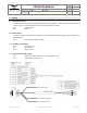
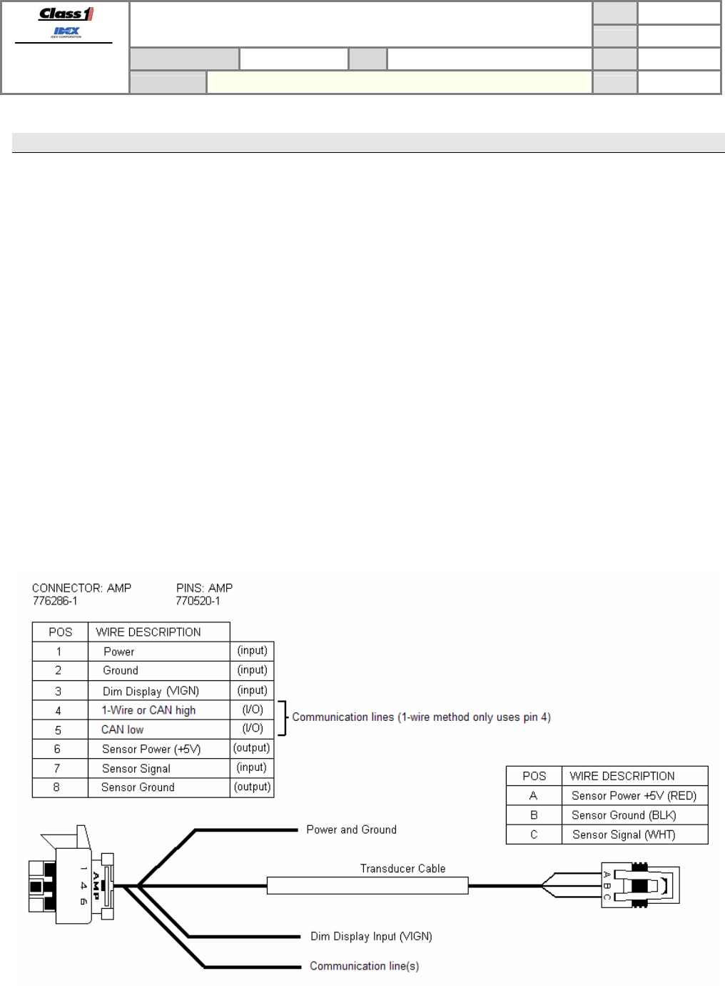
7. Wiring
7.1. Power and Ground
It is imperative that a system utilizing Master and Remote tank level displays connected by the 1-wire data line have a
common ground. The remote displays will not follow the master display otherwise.
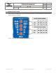
Pin 1 System voltage
Pin 2 Ground
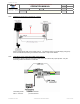
7.2. Dim Function
The LEDs on the tank level display can be dimmed to a user selectable dim setting by applying system voltage to the
Dim display Input.
Pin 3 Dim display input (system voltage)
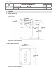
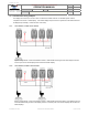
7.3. Transducer Connection
Pin 6 Sensor power (+5)
Pin 7 Sensor signal
Pin 8 Sensor ground
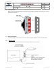
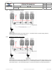
7.4. Communication Data Line(s)
Pin 4 CAN high communication line (or 1-wire communication line)
Pin 5 CAN low communication line