Intelli-Tank Water/foam tank level display with ‘Drip’ Empty Contents …………………………………………………. 1 Revision log …………………………………………………. 2 Overview …………………………………………………. 3 Operation …………………………………………………. 4 Installation …………………………………………………. 6 Wiring …………………………………………………. 8 Calibration …………………………………………………. 10 Dim function …………………………………………………. 13 Self test …………………………………………………. 13 Passwords …………………………………………………. 14 Troubleshooting ………………………………………………….
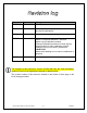
Rev 021502 Date 15 Feb 2002 Changes Initial release. 050304 3 May 2004 Added expanded step-by-step instructions for 5 and 9 point calibrations. 092204 22 Sept 2004 Added “drip” empty indication description. 062805 28 June 2005 Added revision log and “new information” symbol. Added “incomplete calibration” indication. Added 1-point calibration method. Changed calibration procedure to show step-bystep procedure for each calibration method. Changed “set unit as remote” password to LRLR LRLR.
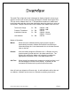
The Intelli-Tank 4 light tank level is designed to display a liquid’s volume to an eighth of a tank level accuracy through 180-degree viewable ultra-bright LEDs. The unit set as a Master uses a 0 – 5 PSI pressure transducer to obtain tank level information and then relays that information along the data line to units set as Remotes. Multiple Remote units can be linked to the Master tank level unit.
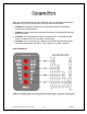
When the unit is first powered up the LEDs will cycle on individually starting with the bottom LED (LED 1) and then the LEDs will show current status. • A Master unit properly connected to a functioning transducer will display current tank level information. • A Master unit not connected to a pressure transducer will alternately flash the bottom two LEDs. • A Remote unit connected to a Master unit (through the 1-wire data line) will mimic the Master unit’s LED condition and flash rate.
Miscellaneous indications: Condition LED 4 LED 3 LED 2 LED 1 Invalid calibration AlternaFLASH AlternaFLASH Incomplete Fast FLASH Fast FLASH calibration EEPROM error AlternaFLASH AlternaFLASH Signal voltage above AlternaFLASH AlternaFLASH 4.8V Signal voltage below AlternaFLASH AlternaFLASH .4V Remote “NO DATA” AlternaFLASH AlternaFLASH User Error (wave off) ON ON 4 quick cycles ON ON The tank level has two flash rates: FAST (1.6Hz) and SLOW (.8Hz).
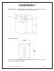
Intelli-Tank display The display requires a cutout as shown. The unit is water tight and may be mounted in any location on the operator’s panel. Outer bezel dimensions. Before mounting the display and adhering the label insure that the unit is situated correctly (TOP is UP). Refer to the drawing for orientation.
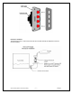
Pressure Transducer The transducer has a ¼” NPT mount and must be mounted vertically as depicted to insure an accurate reading.
Power and Ground It is imperative that a system utilizing Master and Remote tank level units connected by the 1-wire data line have a common ground. Pin 1 Vehicle power Pin 2 Ground Dim Function The LEDs on the tank level unit can be dimmed to a user selectable dim setting by applying vehicle voltage to the Dim display Input.
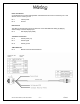
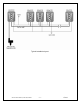
Typical installation layout.
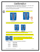
The Intelli-Tank display can be calibrated four different ways: 1-point and 2-point (level calibration), 5-point and 9-point (volume calibration). To enter calibration mode use a magnet and activate the magnetic switches in the order of the appropriate password. The display has two magnetic switches (left and right). The magnetic switches are activated by using a magnet and touching the front of the display on either side of LED 2.
The calibration process can be cancelled at any time by activating the LEFT magnetic switch. 1 Point Calibration 1 point calibration only calibrates the full point. The empty calibration is always set to 0.55V (approximately 1.5 inches of liquid). 1. Make certain that the tank is FULL. 2. Enter the password RLLR LRRL. The unit will respond by flashing the top LED twice. The unit will then revert to normal operation by displaying FULL (all LEDs on). 2 Point Calibration 3. Enter the password RLLR LLRL.
9 Point Calibration 1. Enter the password RLLR RLLR. The unit will respond by flashing the two center LEDs nine times. The unit will then begin cascading the LEDs from top to bottom (drip). 2. Make certain that the tank is EMPTY and then activate the RIGHT switch to store that point. The unit will flash the top LED and then begin flashing the bottom LED. 3. Fill the tank to the one-eighth point and then activate the RIGHT switch. The unit will flash the top LED and then turn on the bottom LED. 4.
Dimming the Display The display can be dimmed by applying VIGN to pin 3 (Dim Display input). To select the dim level of the display use the magnetic switches to enter the password RLLR LLLR all of the LEDs will come on. Hold the magnet against the RIGHT switch and the display will either brighten or dim. Release the magnet and again hold it against the RIGHT switch and the display’s brightness will move in the opposite direction. When the dim level is at the desired point activate the LEFT switch.
RLLR LRRL 1 point calibration RLLR LLRL 2 point calibration RLLR LRLR 5 point calibration RLLR RLLR 9 point calibration RLLR LLRR Self test LRLR LRLR Configure unit as Remote unit RLLR LLLR Configure dim level Software revision check Hold a magnet on the LEFT magnetic switch while powering the unit. The LEDs will display the software revision. (Use the chart below to decipher). Example. (LED 4 – OFF, LED 3 – ON, LED 2 – OFF, LED 1 – ON) = Ver 1.
Condition Evaluate Bottom two LEDs alternate flashing. Check transducer wiring. Ensure +5V at pin A, ground at pin B and at least .4V at pin C (Signal). Unit fails self test, LED 1 flashing. Top two LEDs alternate flashing. Check transducer wiring. Ensure +5V at pin A, ground at pin B and no more than 4.8V at pin C (Signal). Unit fails self test, LED 1 on. Middle two LEDs alternate flashing. Perform self test. If it fails with LED 3 on replace unit. Outer two LEDs alternate flashing.
Condition Evaluate The bottom two LEDs are on and occasionally they go out and the top two flash and then return to the bottom two LEDs on (or viceversa). (REMOTE). Check for large noise spikes on the data line. Insure that the unit’s ground potential is the same as the Master’s. Insure that the data line is not chaffed and making contact with other electrical wires. The points calibrated Self test the unit to check for any malfunctions. seemed to have Check the pressure transducer for problems.
55 Remote 91 Dim adjust 92 2-point cal 93 Self test 95 5-point cal 96 1-point cal 98 Default master 99 9-point cal Intelli-Tank Manual (106759)071006 – 17 – Class 1
Intelli-Tank Manual (106759)071006 – 18 – Class 1