
User Manual

THE CONTINUOUS POWER COMPANY
Page 14
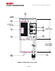
SIGNALS AND INTERFACING
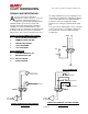
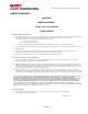
t the rear of the unit are two DB-9
subminiature, female connectors. These are
provided for communications links to a
computer or sophisticated monitoring device.
SIGNAL provides open-collector outputs that
typically signal Utility Interrupt and Low Battery
conditions. A system shutdown feature is also
available on this port. Applying a short between Pin
6 and Pin 7 will cause the system to shutdown in
battery mode. This conserves the battery life once
an orderly shutdown has been accomplished. The
system may be configured to shutdown by applying
a +5 to +12V signal across the appropriate pins.
Contact the factory for configuration details.
RS232 is a true computer communications signal
port.
The open-collector signal outputs can be converted
to dry contact closures, as an option. Below is the
pin out of the two connectors with their default
assignments:
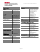
OPEN-COLLECTOR CONNECTOR (SIGNAL)
2- UTILITY INTERRUPTED SIGNAL
4- COMMON SIGNAL RETURN
5- LOW BATTERY SIGNAL
6- + UPS SHUTDOWN
7- - UPS SHUTDOWN
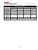
RS232 CONNECTOR
2- TRANSMITTING DATA (TX)
3- RECEIVING DATA (RX)
6 & 8- DATA SET READY
5- SIGNAL GROUND
A
DB-9F
SYSTEM
SHUTDOWN
-
+
5
6
9
1
LOW BATTERY
UTILITY INTERRUPTED
SIGNAL: OPEN-COLLECTOR CONTACT
CONNECTOR
DB-9F
SYSTEM
SHUTDOWN
-
+
5
6
9
1
INVERTER ACTIVE
LOW BATTERY
UTILITY INTERRUPTED
SIGNAL: DRY CONTACT CLOSURE (OPTION)
CONNECTOR
RS232 CONNECTOR
GND
5
3
TX
RX
2
6
8
DB-9F
1KΩ
+5V
DSR