
User Manual

© Copyright 2013. All rights reserved.
Installation Steps, continued
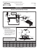
3. For distribution systems with unequal length disposal trench lines, use the chart provided to determine the
correct ow rate for the diameter hole that must be eld drilled in the ow control washer. Install washers
into the unions as shown in Figure 2.
4. For distribution systems with equal length disposal trenches then drill 1/4" diameter holes (or larger) in all washers.
5. The manifold should be installed in a 24" or 30" diameter access riser with lid.
6. Bed manifold area with 2" of pea gravel. Manifold should be installed level.
7. The incoming line should be pressurized with at least 3' of distal pressure. The manifold should be
connected to the pump line with a 2" union PVC pipe connection.
8. Outlet pipes contain 3' of exible PVC pipe with a 1-1/4" diameter connection. Run 1-1/4" or larger pipe
away and downgrade from manifold to individual trenches (check local codes).
9. Check that all connections are glued appropriately and watertight. Backll around manifold with pea gravel
until 2" pipe is almost buried. This will ensure the manifold does not move and stays close to level.
10. Place access riser and lid around manifold and nish backlling. Landscape as desired.
All Clarus Environmental products must be installed and maintained in accordance with all applicable codes.
Product information presented here reflects conditions at time of publication. Consult factory regarding
discrepancies or inconsistencies.
3649 Cane Run Rd. • Louisville, KY 40211-1961 • (800) 928-7867 • FAX: (502) 774-3624
www.clarusenvironmental.com
Your Peace of Mind is Our Top Priority
®
Maintenance Instructions
The Spider Valve should be inspected and maintained as needed during routine maintenance inspections of the
system. Please follow the steps below to properly inspect and maintain the Spider Valve.
1. Please wear appropriate safety apparel and equipment when maintaining any wastewater component or system.
2. Remove the riser lid to access the Spider Valve.
3. Locate the 1/2” PVC union connections (see gure 2) and unscrew them one at a time to inspect the ow
control washer orices for debris or obstructions. NOTE: It is important to inspect one union and ow
control washer at a time so that ow control washers with different orice diameters are not mistakenly
installed within an incorrect union.
4. If the orice is obstructed, remove the ow control washer and use a nylon blush to clean it with water.
5. Reinstall the ow control washer within the correct union and reassemble.
6. Repeat steps 3-5 with each union until all have been inspected and cleaned as necessary.